


8.7
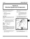
Section 8
Electrical System and Components
8
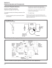
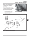
Battery
Battery (R)
_
+
Starter (L/R)
Run (R)
Ignition Kill (W)
Accessory (Y)
Key Switch
Ground (B)
Ground
Starter
Battery
Accessory
Key Switch
Ignition Kill
Run
Connector
L
R
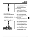
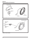
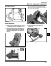
Starter
Solenoid
Stud
Starter
Solenoid
Tang
Starter
Assembly
Accessory
Terminal
(+) (Y)
Regulator
Rectifier
AC
B+
AC
Regulator
Connector
Battery (+) (P)
Stator AC (W)
Spark Plug #2
Cylinder
Spark Plug
#1 Cylinder
Flywheel
Stator
Assembly
Ignition
Module
Intake
Manifold
Screw
Blower Housing
Safety Switch
W
Ignition Kill
Carburetor
Assembly
Intake
Manifold
Screw
Fuse
Y
Ground B
Carburetor
Solenoid
Ignition
Module
Coolant Temp. Gauge
W
Coolant
Temp. Switch
Oil Pressure
Switch
Oil Sentry Light
Coolant
Temp. Over-
heat Alarm
W
CONNECTOR LAYOUT
B
R
+
_
O
Ground-To-Kill Lead (White)
Diode
Key Switch
Optional
Oil Sentry
TM
Switch
(Indicator Light)
Optional
Oil Sentry
TM
Switch
(Shutdown)
12 V. Battery
Solenoid
Starter
Lights
Y
B
3 Amp/70 Watt
Flywheel Stator
Ignition
Modules
Spark
Plug
R
L
R
A
S
GND
Light
Optional
Fuse
Optional
Ammeter
Spark
Plug
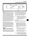
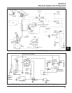
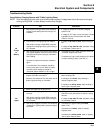
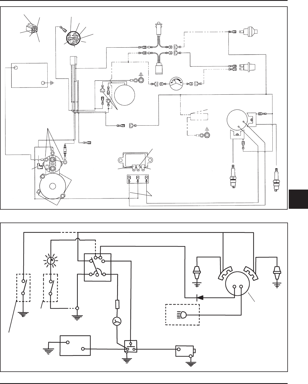
Figure 8-6. Wiring Diagram - 15/20/25 amp Regulated Battery Charging System.
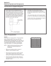
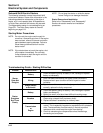
Figure 8-7 Wiring Diagram - 3 amp Unregulated Battery Charging System/70 Watt Lighting.
B