


11.3
Section 11
Reassembly
11
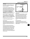
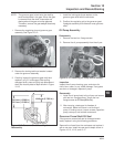
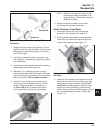
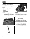
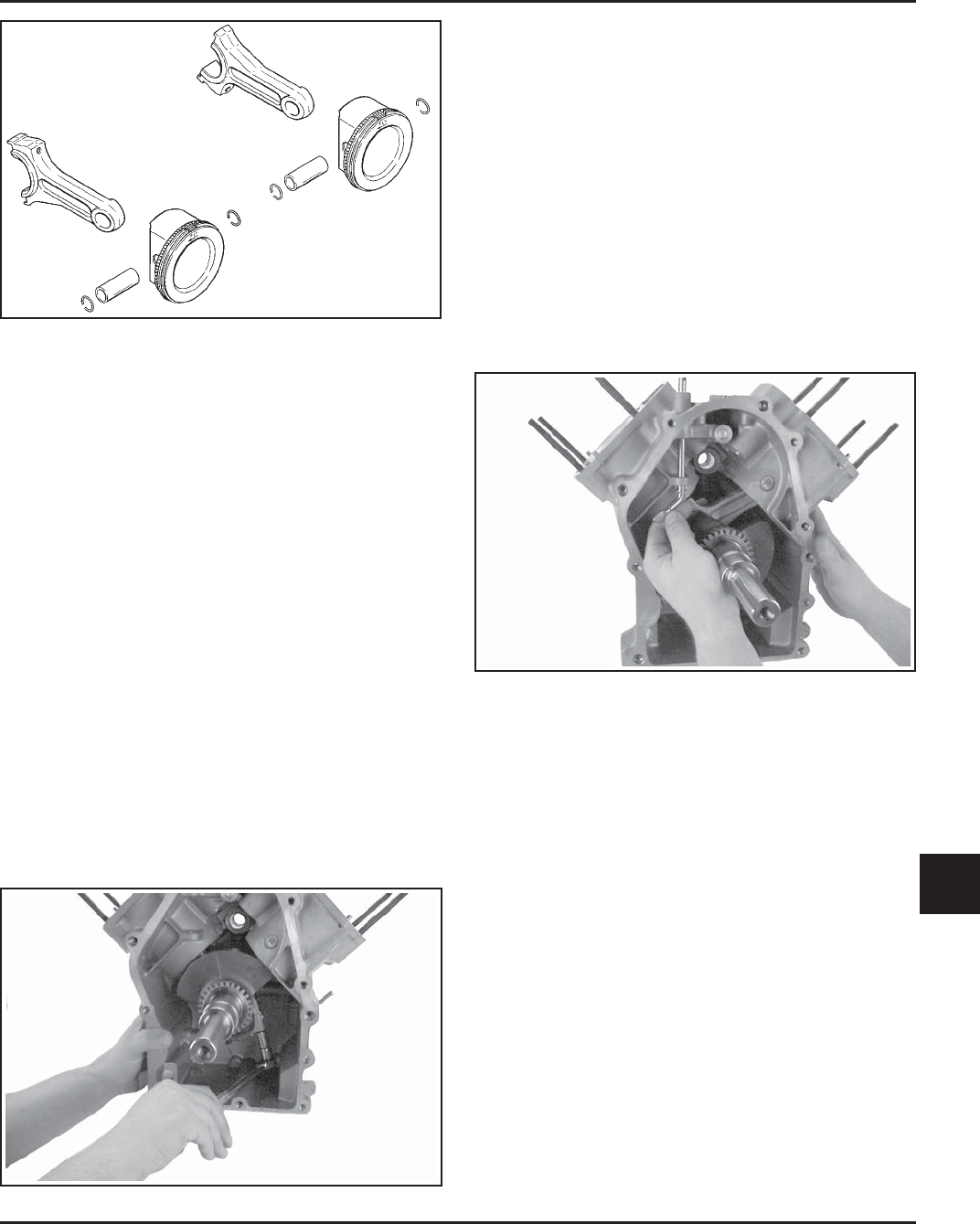
Figure 11-5. Proper Piston Connecting Rod
Orientation.
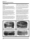
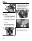
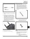
1. Stagger the piston rings in the grooves. The end
gaps of the top two rings should be 180° apart and
perpendicular to the rail end gaps, which should
also be 180° apart.
2. Lubricate cylinder bore, piston, and piston rings
with engine oil. Compress the rings using a piston
ring compressor.
3. Lubricate the crankshaft journals and connecting
rod bearing surfaces with engine oil.
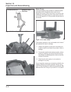
4. Make sure ‘‘Fly’’ stamping on piston is facing
towards the flywheel side of the engine. Using the
grip end of a rubber grip hammer, bump the piston
down into the bore. Do not pound on piston.
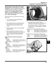
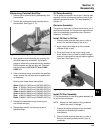
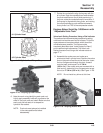
5. Install the inner rod cap to the connecting rod
using the two 6 mm straight shank hex. flange
screws. Torque the screws in increments to
11.3 N·m (100 in. lb.). Illustrated instructions
are also provided in the service rod package.
NOTE: Make sure to align the chamfer of the
connecting rod with the chamfer of its
mating end cap. The chamfer should be
toward the outside.
6. Repeat the above procedure for the other
connecting rod and piston assembly.
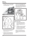
Install Governor Cross Shaft
1. Lubricate the governor cross shaft bearing
surfaces in the crankcase with engine oil.
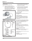
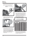
2. Slide the small lower washer onto the governor
cross shaft and install the cross shaft from the
inside of the crankcase. See Figure 11-7.
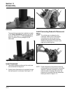
Cylinder #1
Cylinder #2
Figure 11-6. Torquing Rod Cap Bolts.
Figure 11-7. Installing Governor Cross Shaft from
the Inside.
3. Install the nylon washer onto the governor cross
shaft, then start the push-on retaining ring. Hold
the governor shaft up in position, place a 0.25
mm (0.010 in.) feeler gauge on top of the nylon
washer, and push the retaining ring down the
shaft to secure. Remove the feeler gauge, which
will have established the proper end play. See
Figure 11-8.