


11.12
Section 11
Reassembly
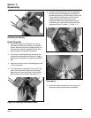
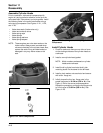
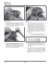
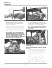
Figure 11-33. Depressing To Bottom Limit of Lifter
Plunger Travel.
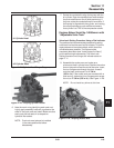
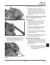
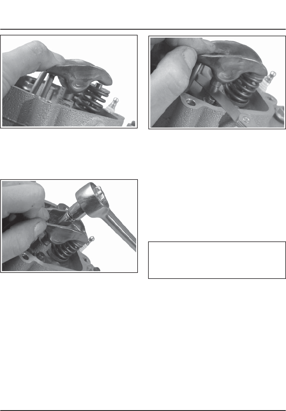
10. With the lifter still compressed, slowly tighten
the rocker arm fastener (clockwise) until the free
end of the rocker arm just makes contact with the
end of the valve. See Figure 11-34.
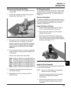
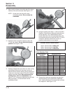
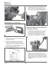
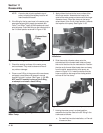
Figure 11-35. Determining Clearance with Feeler
Gauge.
12. Add 0.004" to the dimension from step 11 and
record the total. This is the total shim thickness
required for proper valve lash. Refer to the
following table and determine which combination
of shims will get you closest to that total. If you
need additional shims, beside those taken out
during disassembly, refer to the parts manual and
order the shim kit. The kit contains a sufficient
assortment to cover all possible combinations on
one engine.
NOTE: Do not use the shim selection chart on
page 11.10 when using this procedure.
Available Shim Thickness & Identification:
.004 in. Shims contain a Blue Line
.008 in. Shims contain a Red Dot
.020 in. Shims contain a Black Dot
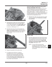
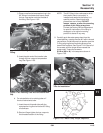
13. Remove the rocker arm assembly and place the
selected shims on the screw/stud, below the
pivot. Lightly lubricate all moving/contact surfaces
with engine oil.
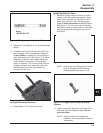
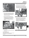
14. Reassemble the rocker arm and pivot assembly
(with shims) to the head (see Figure 11-36) and
seat the push rod. Torque the fastener; 11.3 N·m
(100 in. lb.) for a hex. flange screw, or 17.3 N·m
(153 in. lb.) for a lock nut. See Figure 11-37.
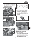
Figure 11-34. Establishing ‘‘0’’ Lash/ ‘‘0’’ Preload.
11. While still maintaining pressure on rocker
arm/lifter, use a feeler gauge and determine the
existing clearance between the base of the pivot
and adjacent surface of the cylinder head. See
Figure 11-35. Record this dimension.
5/04