


8.6
Section 8
Electrical System and Components
Test
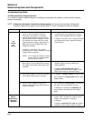
1. If one side is not firing, check all wiring,
connections, and terminations on that side. If
wiring is okay, replace ignition module and retest
for spark.
If the tester shows spark, but the engine misses
or won't run on that cylinder, try a new spark plug.
If neither side is firing, recheck position of ignition
switch and check for shorted kill lead.
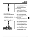
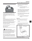
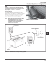
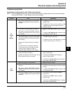
1. Test for spark on both cylinders with Kohler
ignition tester, Part No. 24 455 02-S. Disconnect
one spark plug lead and connect it to the post
terminal of the tester. Connect the clip to a good
ground, not to the spark plug. Crank the engine
and observe the tester spark gap. Repeat the
procedure on the other cylinder. Remember to
reconnect the first spark plug lead.
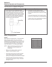
Conclusion
Ground Clip
Post Terminal
Test Procedure for Standard CD Ignition
Battery Charging System
General
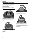
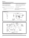
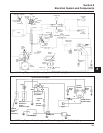
Most engines are equipped with a 15 amp regulated
battery charging system. Some have a 25 amp
regulated battery charging system. See Figure 8-6 for
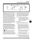
the 15/25 amp system diagram. Some have a 3 amp
unregulated system with optional 70 watt lighting
circuit. See Figure 8-7 for 3 amp system diagram.
NOTE: Observe the following guidelines to avoid
damage to the electrical system and
components:
• Make sure the battery polarity is correct. A
negative (-) ground system is used.
• Disconnect the plug from the rectifier-regulator
and the battery cables before doing electric
welding on the equipment powered by the engine.
• Prevent the stator (AC) leads from touching or
shorting while the engine is running. This could
damage the stator.
Wiring Color Codes
B
L
R
Y
W
P
O
L/R
Black
Blue
Red
Yellow
White
Purple
Orange
Blue/Red