


11.27
Section 11
Reassembly
11
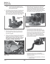
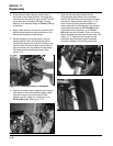
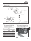
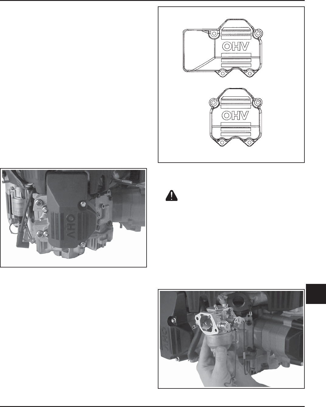
Figure 11-93. Attaching Linkages onto Carburetor.
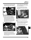
Checking Valve Train
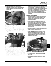
1. Rotate engine to check for free operation of the
valve train. Check the clearance between valve
spring coils at full lift. Minimum allowable
clearance is 0.25 mm (0.01 in.). If engine seems
tight or spring coils do not have proper clearance,
repeat the valve lash adjustment procedure.
Install Valve Covers
1. Make sure the sealing surfaces of cylinder heads
and valve covers are clean and free of all old
gasket material.
2. Position new gaskets on the gasket surfaces of
the valve covers and press them onto the molded
locating pins.
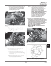
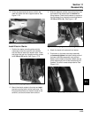
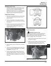
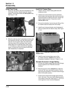
3. Install the valve cover with the breather assembly
on the #1 side, and finger tighten the four
mounting screws. Make sure the gasket stays
aligned. See Figure 11-91.
Figure 11-91. #1 Side Valve Cover.
4. Install the other cover on the #2 side in the same
manner.
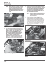
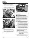
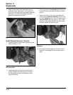
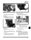
5. Torque the mounting screws of each cover in the
sequence shown to 6.2 N·m (55 in. lb.). Do not
overtighten. See Figure 11-92.
6. Route the breather tube through the opening in
the lower blower housing, if it was removed from
the breather fitting in the valve cover. Connect the
tube to the outlet of the breather and secure with
the clamp.
Figure 11-92. Valve Cover Torque Sequence.
Install Carburetor
WARNING: Explosive Fuel!
Gasoline may be present in the carburetor and fuel
system. Gasoline is extremely flammable and its
vapors can explode if ignited. Keep sparks and other
sources of ignition away from the engine.
1. Install the carburetor gasket. Make sure all holes
are aligned and open.
2. Attach the choke linkage and the throttle linkage
with dampening spring into their lever hole
locations on the carburetor. See Figure 11-93.
4
1
3
2
2
3
1
4