


8.5
Section 8
Electrical System and Components
8
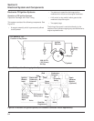
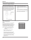
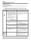
Figure 8-5. Capacitive Discharge Ignition Module.
Operation: As the flywheel rotates, the magnet
grouping passes the input coil (L1). The corresponding
magnetic field induces energy into the input coil (L1).
The resultant pulse is rectified by D1 and charges
capacitor C1. As the magnet assembly completes its
pass, it activates the triggering device (L2), which
causes the semiconductor switch (SCS) to turn on.
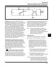
With the device switch “ON,” the charging capacitor
(C1) is directly connected across the primary (P) of the
output transformer (T1). As the capacitor discharges,
the current initiates a fast rising flux field in the
transformer core. A high voltage pulse is generated
from this action into the secondary winding of the
transformer. This pulse is delivered to the spark plug
gap. Ionization of the gap occurs, resulting in an arc at
the plug electrodes. This spark ignites the fuel-air
mixture in the combustion chamber.
Troubleshooting CD Ignition Systems
The CD ignition systems are designed to be trouble
free for the life of the engine. Other than periodically
checking/replacing the spark plugs, no maintenance or
timing adjustments are necessary or possible.
Mechanical systems do occasionally fail or break
down, however, so the following troubleshooting
information is provided to help you get to the root of a
reported problem.
CAUTION: High Energy Electric Spark!
The CD ignition systems produce a high energy
electric spark, but the spark must be discharged, or
damage to the system can result. Do not crank or run
an engine with a spark plug lead disconnected. Always
provide a path for the spark to discharge to ground.
D1
C1
T1
Spark
Plug
P
S
SCS
L2
L1
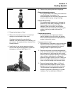
Reported ignition problems are most often due to poor
connections. Before beginning the test procedure,
check all external wiring. Be certain all ignition-related
wires are connected, including the spark plug leads.
Be certain all terminal connections fit snugly. Make
sure the ignition switch is in the run position.
NOTE: The CD ignition systems are sensitive to
excessive load on the kill lead. If a customer
complains of hard starting, low power, or
misfire under load, it may be due to excessive
draw on the kill circuit. Perform the
preliminary test which follows.
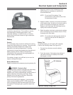
Preliminary Test
To be certain the reported problem is in the engine
ignition system, it should be isolated from the unit.
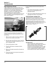
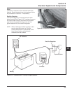
1. Locate the plug connectors where the wiring
harnesses from the engine and unit are joined.
Separate the connectors and remove the white
‘‘kill’’ lead from the engine connector. Rejoin the
connectors and position or insulate the kill lead
terminal so it cannot touch ground. Try to start*
the engine to verify whether the reported problem
is still present.
a. If the problem is gone, the electrical system on
the unit is suspect. Check the key switch,
wires, connections, safety interlocks, etc.
b. If the problem persists, follow the test
procedure on the next page. Leave the kill lead
isolated until all testing is completed.
*NOTE: If the engine starts or runs during any of the
testing, you may need to ground the kill lead
to shut it down. Because you have interrupted
the kill circuit, it may not stop with the switch.