


11.17
Section 11
Reassembly
11
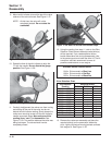
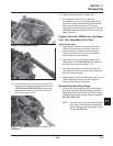
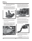
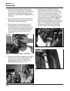
from the crankshaft. Orient the parts as shown in
Figure 11-54 while tightening. Torque the six intake
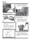
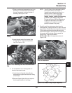
manifold mounting screws in two stages; initially to
7.4 N·m (66 in. lb.) then to 9.9 N·m (88 in. lb.) in
the sequence shown in Figure 11-55.
Figure 11-54. Ground Lead(s) Installation/Position.
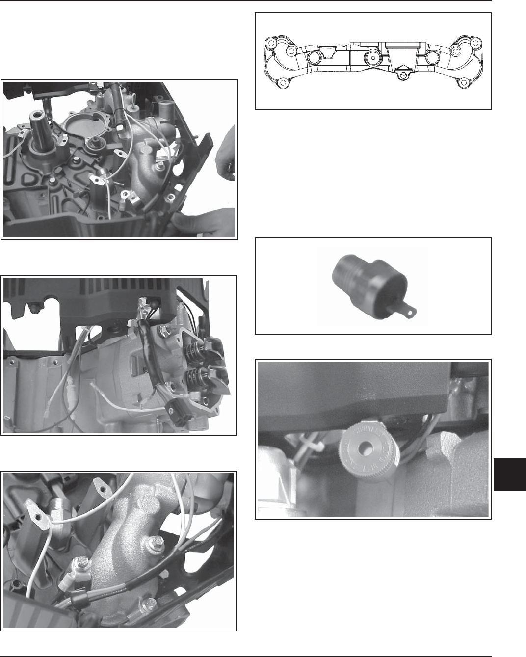
Figure 11-55. Intake Manifold Torque Sequence.
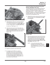
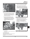
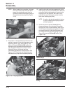
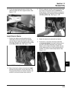
3. Install and tighten the pipe plug or temperature
warning switch, if removed previously from the
threaded port of the intake manifold. Use pipe
sealant with Teflon
®
(not Teflon
®
tape) on the
threads. Torque to 22.6 N·m (200 in. lb.). Connect
the wire leads to the safety interlock switch and
the temperature warning switch or audible alarm,
as equipped.
Figure 11-56. Temperature Switch.
Figure 11-57. Audible Alarm.
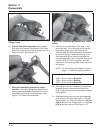
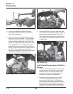
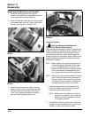
Install Water Pump, Drive Belt and
Transfer Tube Assembly
1. Remove the protective tape from over the keyway
end of the camshaft. Make sure the keyway and
the end of the camshaft are clean and free of any
nicks or damage. Install and fully seat the key
squarely into the keyway. Test fit the cam pulley
onto the shaft and key; it must slide on without
force or restriction. Remove the pulley.
1
5
6
3
4
2
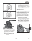
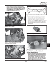
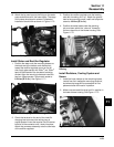
Figure 11-52. Wiring Harness (Top) Routing with
Hose in Place on Fitting.
Figure 11-53. Wiring Harness out Through
Openings in Lower Housing.
5/04