


11.9
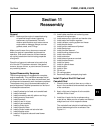
Section 11
Reassembly
11
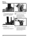
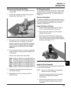
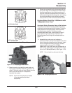
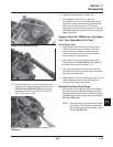
Figure 11-24. Cylinder Head Torque Sequence.
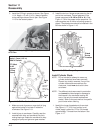
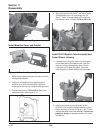
Figure 11-25. Torquing Cylinder Heads.
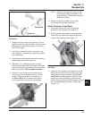
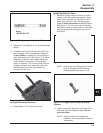
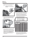
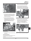
6. Note the mark or tag identifying each push rod.
Lightly apply assembly lubricant or grease to the
ends of the push rods and install. Make sure that
each push rod ball seats in its respective
hydraulic lifter socket.
NOTE: Push rods must always be installed
in the same position as before
disassembly.
# 2 Cylinder Head
# 1 Cylinder Head
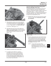
7. Rotate the crankshaft to align the keyway with the
#1 cylinder. Rock the crankshaft and note whether
the push rods/lifters on the #1 side are moving. If
they are, rotate the crankshaft one full revolution. If
the keyway is aligned with the cylinder, and rocking
the crank produces no push rod/lifter movement,
that cylinder is at TDC of the compression stroke.
Engines Below Serial No. 34065xxxxx with
“Adjustable Valve Train”
Valve Lash Setting Procedure Using a Dial Indicator
The preferred and recommended procedure for setting
valve lash involves the use of a dial indicator. This is the
most precise and accurate method, which should be
utilized whenever possible. The lifters must be
completely bled down (see ‘‘Install Hydraulic Lifters’’)
prior to performing this procedure. The Valve Lash
Setting procedure not using a dial indicator starts on
page 11.11.
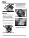
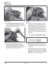
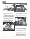
8. Assemble the rocker arms and rocker arm
pivots onto the #1 cylinder head. Position the rocker
arm on the push rod and the end of the valve. Insert
the hex. flange screw through the pivot, thread it
onto the head, and torque it to 11.3 N·m
(100 in. lb.). If the rocker arms are mounted with a
stud and nut, instead of a hex. flange screw, torque
the nut to 17.3 N·m (153 in. lb.). See Figure 11-26.
NOTE: Do not install any shims at this time.
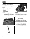
Figure 11-26. Torquing Rocker Arm.
1
3
2
4
3
1
4
2
5/04