


9.12
Section 9
Disassembly
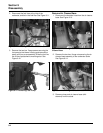
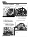
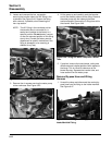
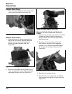
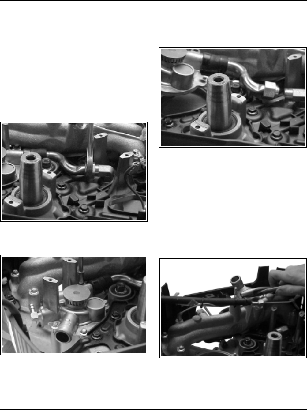
Figure 9-44. Removing Hex. Cap Section.
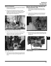
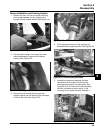
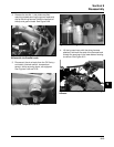
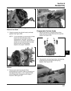
3. Remove the six screws securing the water pump
to the crankcase. See Figure 9-45.
Figure 9-45. Removing the Six Water Pump Screws.
2. Loosen and unscrew the hex. cap section,
securing the transfer tube to the 90° fitting in the
crankcase. See Figure 9-44. Support the fitting
with a wrench, if possible, when loosening the
hex. cap section.
NOTE: The 90° fitting in the crankcase, which
the transfer tube is connected to, is
sealed and installed at the factory in a
specific position. Do not loosen, remove,
or alter the mounted position of this fitting
at any time. Contact the factory service
department for specific instructions if the
fitting is damaged, or its mounting is
affected in any way.
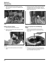
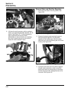
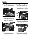
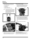
Figure 9-46. Lifting Out Water Pump and Transfer
Tube.
5. If required, remove the hose clamps, noting size
differences and installed positions with respect to
the tangs. This is critical for clearance to the
blower housing. Separate the transfer tube, and
hose section from the water pump.
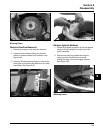
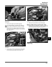
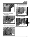
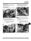
Remove By-pass Hose and Wiring
Harness
1. Unseat the clamp and disconnect the coolant by-
pass hose from the fitting on the intake manifold.
See Figure 9-47.
Figure 9-47. Removing Coolant By-pass Hose from
Intake Manifold Fitting.
4. Lift the pump up and carefully work the ferruled
end of the transfer tube out of the fitting. Remove
the water pump with the tube and the hose
section attached. Remove the O-Ring from within
the channel. See Figure 9-46.