


CJ2A Operation and Care
Manual -- Plowing Method, PTO and Vehicle Speeds)
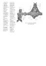
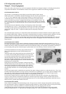
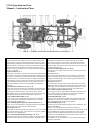
To avoid loss of time and minimize turning at the headlands while plowing a
field, the following procedure is recommended:
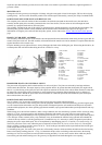
Lay out the field lengthwise in convenient lands or sections as shown by the
back furrows in Fig. 38. The width of the lands will vary according to the field
size; however, make the lands as near ten rods in width as possible. Should the
lands be too narrow, time will be lost in turning at the headlands and in
completing dead furrows; if too wide, time will be lost in driving across the
headlands.
Plow a shallow marker furrow across each end of the field, parallel with and 20
feet from the end, to act as a guide in keeping the headlands straight.
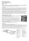
Set up a target at each end of the field to indicate the line of the first back
furrow. Plow a furrow between the headland marks, using the target as a guide
to keep the furrow straight and parallel with the edge of the field. Turn and plow
a second furrow against the first to complete the back furrow. It is advisable to
have the plow set to turn a shallow furrow and use care that the second furrow
does not overlap the first, otherwise an objectionable ridge will be formed the
length of the field. Next adjust the plows for standard depth and plow around the
back furrow until the unplowed space at the side of the field is equal to the width
of the headlands previously marked off.
Throw a new back furrow in the same manner at the next back furrow line and plow around it until the unplowed portion
between the lands equals that which has been plowed around the new back furrow. To reduce driving distance, plow around
the unplowed portion between the two back furrows until it is completed to form a dead furrow. When plowing the dead
furrow, set the plows shallow to prevent forming an objectionable trench the length of the field.
Continue with new lands, started by back furrows, until the width of the unplowed ground at each side of the field equals the
marked-off headlands at each end of the field.
If it is desired, to prevent close turns, the operator may plow one side of a back furrow returning across the field plowing the
opposite side of the next back furrow. Plowing around the two back furrows until the two plowed sections are wide enough to
allow easy turns may save some time.
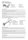
Next plow the headlands around the field. Plow the ground out toward the edge: next time the field should be plowed in toward
the centre. If it is decided to plow “out”, start at the outer edge, plowing around the field until the headlands are completed.
This will leave a dead furrow around the field at the inner edge of the headlands. To plow “in”, start at the inner edge of the
headlands and the dead furrow will be at the outer edge of the field.
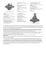
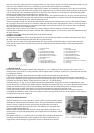
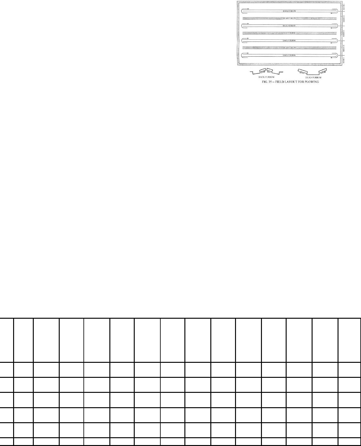
Power Take-Off and Vehicle Speeds
To satisfactorily operate most power-driven equipment, the operator should know the speed of the power take-off shaft or the
belt pulley as well as the vehicle ground speed. A great variety of speeds are made available by the manual governor control,
the gear ratios in the transmission and transfer case and by interchanging the gears in the power take-off housing.
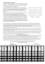
The tables below indicate the speeds for each of the nine positions of the manual governor control. Note that the shaft speeds
are all computed with the vehicle in four-wheel drive and that of the belt pulley in the transmission drive only. Reference to
these tables will be of material assistance especially in the operation of the farm combine or grain seperator.
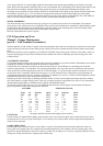
Power Take-off Shaft Speeds (R.P.M.) and Vehicle Ground Speeds (M.P.H.)
Power Take-Off Gear Ratios
20-24 RATIO 24-20 RATIO
Transmission Gear In Transmission Gear In
Low Intermediate High Low Intermediate High
Gove
rnor
Contr
ol
Positi
ons
Transfe
r In
Take-Off
Shaft
RPM
Vehicle
Speed
MPH
Take-Off
Shaft
RPM
Vehicle
Speed
MPH
Take-Off
Shaft
RPM
Vehicle
Speed
MPH
Take-Off
Shaft
RPM
Vehicle
Speed
MPH
Take-Off
Shaft
RPM
Vehicle
Speed
MPH
Take-Off
Shaft
RPM
Take-Off
Shaft
RPM
Engine
Speed
1
Low
High
298
298
2.22
5.40
537
537
4.01
9.75
833
833
6.22
15.13
428
428
2.22
5.40
773
773
4.01
9.75
1200
1200
6.22
15.13
1000
2
Low
High
357
357
2.67
6.48
644
644
4.81
11.71
1000
1000
7.47
18.15
514
514
2.67
6.48
928
928
4.81
11.71
1440
1440
7.47
18.15
1200
3
Low
High
417
417
3.11
7.56
752
752
5.62
13.66
1166
1166
8.72
21.17
600
600
3.11
7.56
1083
1083
5.62
13.66
1680
1680
8.72
21.17
1400
4
Low
High
476
476
3.56
8.65
859
859
6.42
15.61
1333
1333
9.96
24.20
685
685
3.56
8.65
1237
1237
6.42
15.61
1920
1920
9.96
24.20
1600
5
Low
High
536
536
4.00
9.73
967
967
7.22
17.56
1500
1500
11.20
27.22
771
771
4.00
9.73
1392
1392
7.22
17.56
2160
2160
11.20
27.22
1800
6Low 595 4.44 1074 8.02 1666 12.45 857 4.44 1547 8.02 2400 12.45 2000