


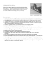

ENGINE MOUNTINGS
The rubber engine mountings, which are attached to the frame side rail brackets and
to the support plate, prevent fore-and-aft motion of the engine, yet allow free
sidewise and vertical oscillation which neutralizes vibration at the source. Keep the
mountings tight. A loose engine may cause vibration, clutch chatter or high fuel level
in the carburetor.
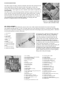
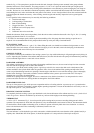
The rubber surface of the mountings partially insulates the engine from the frame. To
assure a positive electrical connection between the engine and the frame, a ground
strap is provided at the right front engine support under the generator. See Fig. 10.
The two attaching screws must be kept tight and the connections clean. A loose or
poor connection may result in hard engine starting, low charging rate of the
generator or sluggish operation of the starting motor.
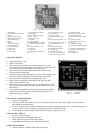
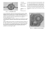
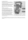
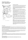
OIL PUMP ASSEMBLY
The oil pump assembly is provided with a pressure relief valve which controls the maximum oil pressure at all speeds.
The standard controlled pressure is 35 lps. at 30 mph. and 10 lbs. at the idle speed of 600 rpm. as registered by the dash gauge.
Pressure may be adjusted by installing or removing shims between the relief plunger spring and the spring retainer. Add shims
to increase the pressure or remove to decrease.
1. Cover Screw
2. Cover
3. Cover Gasket
4. Outer Rotor
5. Shaft and Rotor
6. Body
7. Driven Gear
8. Gasket
9. Gear Retaining Pin
10. Relief Valve Retainer
11. Relief Valve Retainer
Gasket
12. Relief Valve Spring
13. Relief Valve Plunger
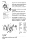
The oil pump drive shaft drives both the pump and
the distributor assembly. See Fig. 2. Should it be
necessary to remove the oil pump assembly, first
remove the distributor cap and carefully note the
position of the rotor to allow reinstallation without
disturbing the ignition timing. When the pump is
installed, use care that the driving key on the end of
the distributor shaft is correctly meshed with the slot
on the end of the pump shaft. To make the
installation without disturbing the ignition timing, the
pump gear must be correctly meshed with the
camshaft gear to allow mesh of the distributor driving
key and slot with the distributor rotor in the original
position. Should it be necessary to reset the ignition
timing, refer to the previous page.
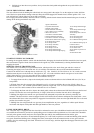
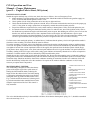
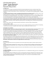
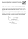
1. Fan Assembly
2. Water Pump Bearing and Shaft Assembly
3. Water Pump Seal Washer
4. Water Pump Seal Assembly
5. Water Pump Impeller
6. Piston
7. Wrist Pin
8. Thermostat Assembly
9. Water Outlet Elbow
10. Thermostat Retainer
11. Exhaust Valve
12. Intake Valve
13. Cylinder Head
14. Exhaust Manifold Assembly
15. Valve Spring
16. Valve Tappet Self-Locking Adjusting Screw
17. Engine Plate - Rear
18. Camshaft
19. Flywheel Ring Gear
20. Crankshaft Packing - Rear End
21. Crankshaft Bearing Rear Drain Pipe
22. Crankshaft Bearing Rear - Lower
23. Valve Tappet
24. Crankshaft
25. Oil Pump and Distributor Drive Gear.
26. Connecting Rod Cap Bolt
27. Oil Float Support
28. Oil Float Assembly
29. Crankshaft Bearing Centre - Lower
30. Connecting Rod Assembly - No. 2
31. Connecting Rod Bolt Nut Lock
32. Crankshaft Bearing - Lower Front
33. Crankshaft Oil Passages
34. Crankshaft Thrust Washer
35. Crankshaft Gear
36. Crankshaft Gear Spacer
37. Timing Gear Cover Assembly
38. Fan and Generator Drive Belt
39. Crankshaft Oil Seal
40. Starting Crank Nut Assembly
41. Crankshaft Carrier Key
42. Fan and Governor Drive Pulley Key
43. Timing Gear Oil Jet
44. Fan, Generator and Governor Drive Pulley
45. Camshaft Thrust Plate
46. Camshaft Gear Retaining Washer
47. Camshaft Gear Retaining Screw
48. Camshaft Gear Thrust Plate Retaining Screw
49. Camshaft Gear