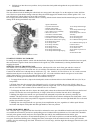
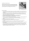
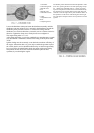
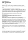
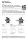
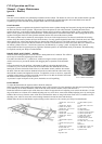
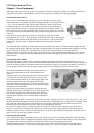
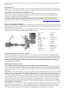
camshaft, Fig. 13. The pump draws gasoline from the fuel tank, through a filtering screen mounted in the pump sediment
chamber and forces it to the carburetor. The pump pressure is 4 ½ lbs. at 16” above the outlet at 1800 rpm. Engine speed.
The sediment chamber can be removed by backing off the thumbscrew nut sufficiently to permit swinging the wire clamp to
one side. The bowl or cover should be washed and wiped dry and the screen dried and then cleaned with a stiff brush. When
reassembling the bowl, make certain that the cork gasket is not broken; reverse it and position it flat on the seat then install the
bowl and tighten the thumb nut securely. After cleaning, start the engine and carefully inspect the bowl to guard against
leakage.
Lack of gasoline in the carburetor may be caused by the following conditions:
• Gasoline tank empty.
• Leaking tubing or connections.
• Bent or kinked tubing.
• Clogged fuel lines – (or frozen).
• Sediment bowl on fuel pump loose.
• Dirty screen.
• Carburetor inlet valve stuck shut.
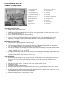
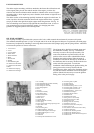
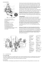
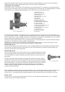
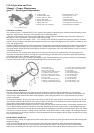
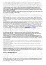
Should the carburetor flood (too much gasoline), check the unit to make certain that the needle valve Fig. 14, No. 8, is seating
properly and that the float No. 9 is not stuck.
CAUTION: Do not attempt repairs which require disassembling of the fuel pump other than cleaning as special care is
required. It is recommended that all fuel pump trouble be taken up with your Willys-Overland Dealer.
FUEL SUPPLY TANK
The capacity of the fuel tank is 10 ½ gal. (U.S.). When filling the tank, care should be used that no foreign matter or water
enters the tank. Once each season, at a time when the fuel supply is low in the tank, remove the drain plug in the bottom to
drain out sediment and water which may have accumulated.
COOLING SYSTEM
The practice of checking the condition of the cooling system of you Jeep while lubricating it will guard against costly delays in
service. Inspecting the condition of the radiator and heater hoses; also the fan belt and water pump will eliminate the possibility
of an overheated engine due to a water leak or loose fan belt.
RADIATOR ASSEMBLY
The radiator is designed to cool the water under all operating conditions however, the core must be kept free from corrosion
and scale and the air passages free of chaff, dust and mud.
At least twice a year flush out the cooling system. A good way to do this is to remove the drain cock at the bottom of the
radiator and that in the cylinder block under the generator. Place a hose in the radiator filler opening and adjust the flow of
water to equal that draining from the two openings. Start the engine and allow it to run until the cooling system is thoroughly
flushed. After flushing it is advisable to install a corrosion inhibitor in the system to prevent rust and scale. This may be
obtained from your Willys-Overland Dealer.
Should the air passages become clogged, do not use a metal tool of any kind to clean them. Use compressed air or water
pressure and clean from the rear, forcing the dirt out through the front of the radiator.
RADIATOR FILLER CAP
The cap is of the pressure type, which prevents evaporation and loss of cooling solution. A pressure up to 4 ½ pounds makes
the engine more efficient by permitting a slightly higher operating temperature. Vacuum in the radiator is relieved by a valve in
the cap which opens at ½ to 1 pound vacuum.
DRAINING COOLING SYSTEM
To completely drain the cooling system, open both drain cocks; that at the bottom of the radiator and also in the cylinder block
under the generator. Remove the radiator cap to break any vacuum which might prevent thorough draining.
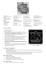
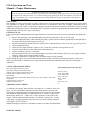
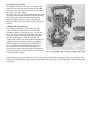
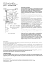
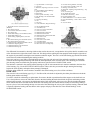
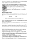
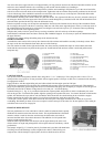
THERMOSTAT
A 145º to 155º F. thermostat, Fig. 2, is used to provide quick warming and to prevent overcooling during normal vehicle
operation. The temperature at which this unit operates is set by the Manufacturer and can not be altered. The thermostat should
be checked first, should sudden overheating occur, as failure to operate will nearly block the water circulation. As a check,
remove the thermostat and if the overheating is eliminated, install a new one.
HEAT INDICATOR
The heat indicator is of the hydraulic type and is connected to a bulb mounted in the water chamber of the cylinder head, by a
capillary tube. Should this unit fail to operate, it should be replaced as it is not practical to either repair or adjust it.