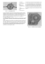
The other gear may be removed in the same manner after removing cover plate. Interchange the gears and reassemble in
reverse order with the long side of the gear hub toward the cover opening. Use care that the shims are replaced in the same
position relative to the bearings from which they were removed. Do not overlook refilling the housing with lubricant.
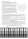
The speed of the output shaft in relation to the vehicle ground speed is important. To aid in the selection of engine speeds and
gear ration positions, refer to the chart on the “Power Take-Off and Vehicle Speeds” page which shows both the shaft and
vehicle speeds through the range of governor controlled engine speeds and in all transmission and transfer case gear positions.
CAUTION: When the vehicle is reversed, the shaft drive will turn in the reverse direction. Some farm machines will be
damaged if reverse driven. When operating trailed equipment, be sure to disengage the power take-off with the shift lever
before reversing the vehicle. Being able to reverse some power driven machines is an advantage to aid in freeing the machine
should it become clogged in operation.
Inspect the power take-off unit periodically and add sufficient lubricant to keep it at filler plug level. Keep the attaching screws
tight at all times and the breather or vent free of dirt.
When using the shaft drive, always install the shield which is provided for the safety of the operator.
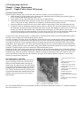
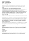
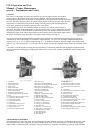
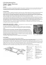
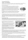
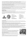
PULLEY DRIVE ASSEMBLY
The pulley drive assembly, with 8” pulley, is driven through the power take-off shaft. It is held in position with four cap
screws and can be quickly removed or installed. Always remove this assembly when it is not in use to avoid damage through
accident.
When operating the pulley drive assembly use care that the vehicle is correctly aligned so the belt runs at the centre of the
pulley. Do not tighten the belt excessively: when too tight, rapid wear of the drive parts of both the machine being driven and
pulley drive assembly may occur. If correctly adjusted the hand brake will hold the vehicle when ample drive tension is placed
on the belt.
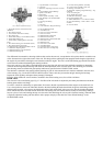
The belt pulley drive is operated from the transmission main shaft, giving the same power and speed ratios that are provided by
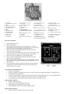
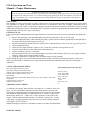
the transmission for the vehicle on the highway. To operate the pulley with the vehicle standing, place the auxiliary (right
hand) transfer case lever in the neutral position, designated as “N” in Fig. 3.
The nine governor controlled engine speeds in conjunction with the transmission gear shift positions provide a large selection
of pulley speeds. Select the governor and transmission gear shift positions that will provide the recommended speed of the
machine being driven. Machines driven below this speed will seldom do a satisfactory job while speeds above normal will
cause rapid wear and are, in some cases, dangerous. The table on the “Power Take-Off and Vehicle Speeds” page is provided
as a guide in selecting the correct control positions to secure the recommended speed.
CAUTION: When the belt drive is used, ground the vehicle with a bar or piece of chain so static electricity is dissipated or
sparks might cause a fire in dusty or inflammable surroundings.
Keep the housing filled with lubricant to the level of the filler plug. (See "Lubrication Chart".)
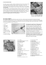
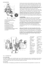
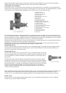
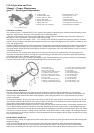
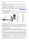
FRONT PULLEY DRIVE UNIT
The front pulley drive unit which may be installed at the rear of the power take-off front or shift unit is used to drive
compressors, pumps, generators, etc., mounted in the vehicle to the right and behind the drivers seat. The 6” pulley may be
wither two or four-grooved for multiple “V”-type belt drives and will deliver up to 23 horsepower.
When multiple drive belts are used it is important that each belt carry an equal share of the load. While this type belt had a
steel core, some stretching may occur, and should one belt break or become damaged, all should be replaced. Should the belts
be removed, mark them to permit reinstallation on the same pulleys from which they were originally removed. Do not tighten
the belts excessively.
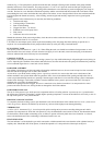
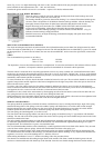
BODY ENCLOSURE
Both front and rear canvas body enclosures are available. The front enclosure may be installed independently and the side
curtains which are mounted on steel frames are hinged to open as doors. The hinge pins may be lifted from sockets to allow
quick removal of the doors.
The rear enclosure is attached to the front top and is provided with curtain lights in each side. A rear curtain with light
completes the enclosure.
As a general rule good quality soap and water will clean the windows in the curtains. Should they become soiled with grease,
kerosene or naphtha may be used.
Avoid the use of benzene, acetone or lacquer thinners, as they will soften the surface and make the windows opaque. Many
spray type window glass cleaners contain some of these ingredients, so avoid their use.
Rubbing the windows with a dry cloth will build up an electrostatic charge which will cause dust to cling to the surface. Such a
charge may be dissipated by blotting the window surface with a clean, damp chamois. After cleaning apply a liberal coating of
automobile or furniture wax as a protection against dirt.
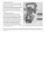
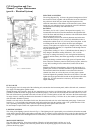
FRONT ENCLOSURE INSTALLATION
First select the front top bow assembly parts. The two side bows are offset at the lower ends and eyes are located near the top
curved ends. The centre connecting bow has an eye located at the centre.
Assemble the centre bow in the two side bows, with the eyes extending toward the windshield and mount the assembly in the
body sockets.
The doors are supported at the top and bottom with hinge support brackets which are not interchangeable as they are made in
rights and lefts.
Select the upper brackets which are made as clamps; the large jaws are formed to span the windshield support and the small
jaws to form the door hinge socket. Select a set of jaws (one having a clamp stud) which will assemble with the hinge socket
vertical and in line with the bracket mounted on the body below.