


CJ2A Operation and Care
Manual -- Proper Maintenance
(part 6 -- Brakes)
BRAKES
The foot or service brakes are hydraulically actuated in all four wheels. The brakes are of the two-shoe, double anchor type and
have chrome-nickle alloy iron drums. The hand brake is mechanically operated through a cable and conduit to an internal
expanding type brake mounted on the propeller shaft at the rear of the transfer case.
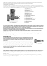
FOOT BRAKES
In operation, pressure is applied to the hydraulic liquid in the master cylinder through the foot pedal, forcing the liquid through
the lines and into the wheel cylinders. The pressure forces the pistons in each wheel outward, expanding the brake shoes
against the drums. As the pedal is further depressed, higher pressure is built up within the hydraulic system, causing the brake
shoes to exert greater force against the brake drums. As the brake pedal is released the brake shoe return springs pull the shoes
together forcing the fluid out of the cylinders and back into the lines toward the master cylinder.
The master cylinder may be reached by removing the five screws in the inspection cover on the toe board below the steering
column. Keep the master cylinder reservoir full at all times. Use only genuine hydraulic brake fluid. Check the level each 1000
miles and use care, when removing the filler cap, that no dirt enters the reservoir. The fluid capacity is approximately ¾ pts.
The hydraulic brake system must be bled whenever a fluid line is disconnected or air enters the system due to low fluid level in
the master cylinder reservoir. A leak in the system may be indicated by a “spongy” pedal. Air trapped in the system is
compressible and does not permit pressure, applied to the brake pedal, to be transmitted solidly to the brakes. Should bleeding
be required, consult your Willys-Overland Dealer.
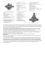
BRAKE SHOE ADJUSTMENT – MINOR
When the brake lining becomes worn the effective brake pedal travel is reduced. The effective
travel may be restored by adjusting the brake shoes.
First make sure that there is ½” pedal travel, without moving the master cylinder piston,
which is necessary to prevent the brakes from dragging due to expansion of the hydraulic
liquid.
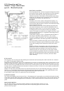
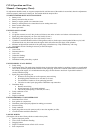
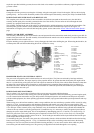
Jack up the wheels to clear the floor. Adjustment is made by relocating the brake shoe
eccentrics Fig. 28. Loosen the lock nut for the forward brake shoe and hold the nut while
turning the eccentric toward the front of the car, with another wrench, until the shoe strikes
the drum. Turn the wheel with one hand and release the eccentric until the wheel turns freely
then hold the eccentric and tighten the lock nut. To adjust the reverse or rear shoe, repeat this
operation except turn the eccentric toward the rear of the car. Do this on all brakes and check
the fluid level in the master cylinder reservoir.
As pressure is equal in all parts of the system, the brakes are self-equalizing
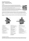
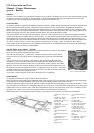
HAND BRAKE
To adjust the hand brake the sequence below should be followed:
Make sure that the brake handle on the instrument panel is fully released. Give due attention to the cable and operating linkage
to see that they do not bind. Should the cable fail to slide freely into the conduit, remove and lubricate it.
Rotate the brake drum until one pair of the three sets of holes are opposite the two adjusting screw wheels in the brake. Use the
edge of the holes as a fulcrum for a suitable adjusting tool or a screw driver, rotate each notched adjusting screw by moving the
handle of the tool away from the centre of the drive shaft until the shoes are snug in the drum. Back off seven notches on each
adjusting screw wheel to secure the correct running clearance between the shoes and the drum.
Should either the foot or hand brakes require relining or other extensive work, contact your Willys-Overland Dealer.
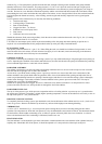
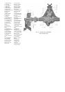
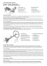
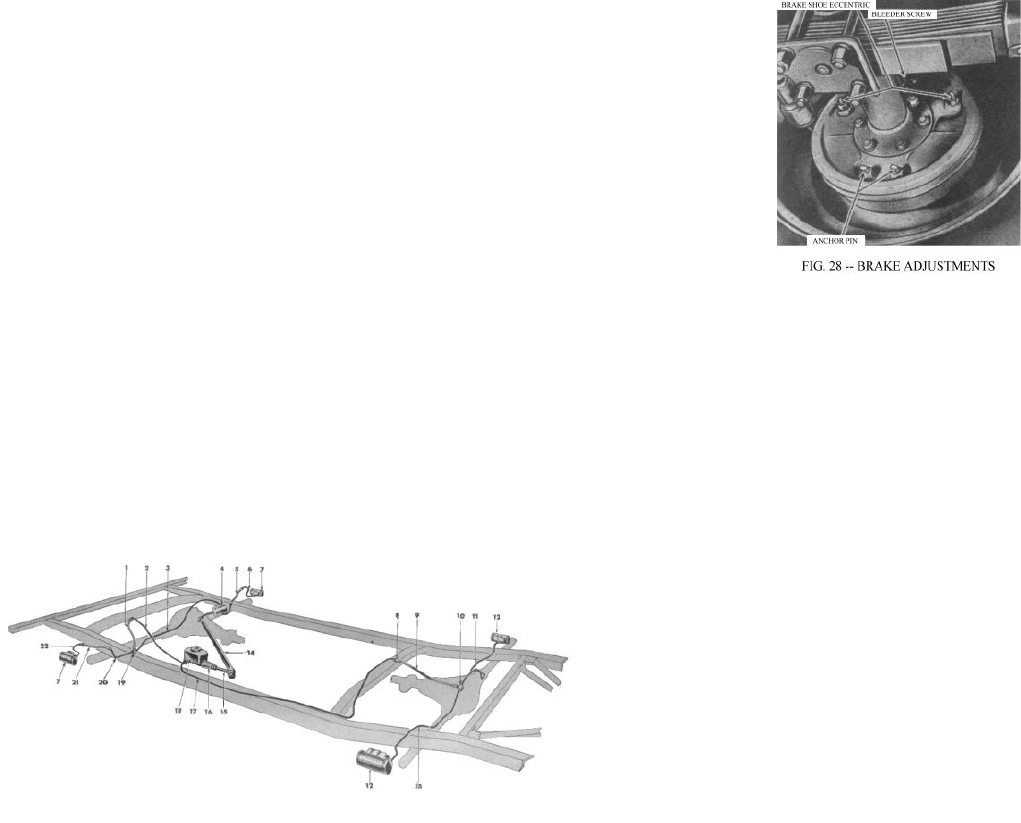
1. Brake Hose - Front Axle to
Frame
2. Brake Tube - Master
Cylinder to Front Hose
3. Brake Tube - Tee to Front
Brake Hose, Right
4. Brake Pedal
5. Brake Hose - Front Axle
6. Brake Tube - Wheel
Cylinder to
Hose
7. Wheel Brake Cylinder -
Front
8. Brake Hose Spring Lock
Clip
9. Brake Hose Assembly
10. Rear Brake Tee
11. Brake Tube - Rear Axle
Tee to
Right Rear Axle
12. Wheel Brake Cylinder -
Rear
13. Brake Tube - Rear Axle
Tee to
Left Rear Brake
14. Brake Pedal Shaft
15. Master Cylinder Eye Bolt
16. Master Cylinder Boot
17. Brake Tube - Master
Cylinder to Rear Hose
18. Brake Master Cylinder
19. Rear Axle Tee
20. Brake Tube - Tee to Left
Front
Brake Hose
21. Brake Hose - Front Axle
22. Brake Tube - Wheel
Cylinder to Hose