


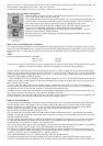

CJ2A Operation and Care
Manual -- Extra Equipment)
Much of the utility of the Jeep is due to the extra equipment which has been designed to adapt it for farming and diversified
occupations and industries. The maintenance and use of this equipment is outlined in the following paragraphs.
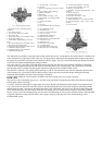
GOVERNOR (KING SEELY)
The governor is a centrifugal type unit which gives precision control of engine speeds.
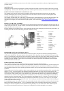
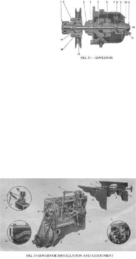
When speed control is not desired it should be disengaged with the twin-pin type clutch No.
1, Fig. 33. Never engage this clutch with the engine running. To operate it pull the cap
outward and rotate it ¼ turn in either direction until you feel the two lugs drop into the
recesses provided. The governor is engaged when the lugs are in the deeper recesses. The
shallow recesses lock it in the disengaged position. Some governor clutches are controlled
by a spring loaded lever mounted at the top of the governor housing the operation of which
is obvious.
The belt tension may be adjusted by raising or lowering the governor in the slotted
mounting holes Fig. 34, No. 11. Keep the pulleys and belt free of dirt and oil. Belt slippage
will effect governor operation and a tight belt may cause rapid wear of the governor shaft
and bearings. Adjust it to allow 1” depression midway between the pulleys with thumb
pressure.
The controlled engine speed may be varied with the hand control mounted on the dash. With this control in against the dash,
the controlled engine speed is 1000 rpm. The speed is increased 200 rpm. Per notch, as the hand control is pulled out. The top
speed is 2600 rpm. In the 9th notch. The hand control is released by turning the handle ¼ turn in either direction.
When the governor is to be used, stop the engine, engage the governor clutch and pull the hand throttle fully out to allow the
governor to take over engine speed control. When the governor clutch is disengaged, release the hand throttle by ¼ turn in
either direction.
GOVERNOR ADJUSTMENT
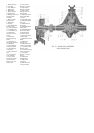
Mechanical adjustment of speed control is obtained by adjusting the length of hand cable control assembly No. 5, Fig. 34.
First check the carburetor throttle rod to make certain the throttle opens and closes fully. Disconnect the accelerator spring and
eliminate any bind or stiffness in the throttle connections and carburetor linkage. Free operation of the throttle is necessary to
prevent surging of the governor when the engine is placed under load. After checking, reconnect and leave it there.
Set the dash hand throttle in the fully open position and leave it
there. All the adjustments are made with the throttle in this
position.
Adjust the length of the spring loaded governor-to-throttle link No.
13 to allow exact assembly between the short or lower governor
lever and the carburetor throttle lever without moving either lever
and with the throttle fully open. The length of the link after
adjustment should be approximately 6” between the centres of the
ball sockets. Tighten the adjustment lock nut and install the spring
loaded governor-to-throttle link.
Engage the governor clutch by turning the control on the pulley
hub until the pins drop into the deeper recesses. Place the governor
hand control, mounted on the instrument panel, in the closed or
“IN” position and check to be sure the hand throttle is fully open.
Start the engine and allow it to run until operating temperature is
reached.
The governed engine speed is controlled by the position of the upper or long governor lever. Adjust the yoke No. 5, Fig. 34 on
the hand control cable and attach it to the governor arm when the arm is positioned to give an engine speed of 1000rpm. Safely
jack up the rear wheels and be sure the front wheel drive is not engaged. When driving the rear wheels in high or direct
transmission gear, the speedometer will read 15 mph. at an engine speed of 1000 rpm.
In some cases it maybe necessary to adjust the surge screw at the rear of the governor to eliminate surge. Should this be
necessary, loosen the lock nut and turn the slotted screw until the engine stops surging when the governor hand control is
suddenly operated from low to high speeds then tighten the lock nut. Use care in making this adjustment: should the screw be
turned in too far, governor speed control will be lost.
GOVERNOR (MONARCH)
Some vehicles are equipped with the Monarch governor. This governor is similar in design and operation to the King Seeley
type described above. However, engagement is through a spring loaded lever control mounted at the top of the governor body.
To engage the drive unlatch the control lever and allow the spring to carry the engaging clutch forward.
When adjusting this governor follow the above instructions in every detail except the adjustment of the spring loaded
governor-to-throttle link No. 13. Adjust this link with approximately 1/16” slack or lost motion. No surge adjustment is