Poppet balls and springs retain the gears in mesh and an interlock prevents shifting into two gears at one time. Should any
trouble be experienced with the transmission assembly, consult your Willys-Overland Dealer.
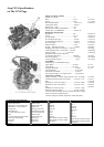
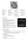
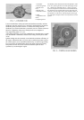
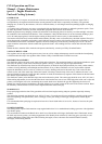
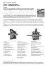
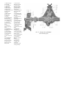
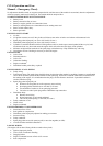
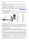
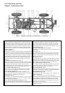
TRANSFER CASE ASSEMBLY
The transfer case Fig. 23 is an auxiliary unit located at the rear of the transmission. It is essentially a two speed transmission,
which provides a low and direct gear, also a means of connecting the drive to the front axle. The shifting mechanism is located
on the transfer case for engaging and disengaging the drive to the front axle, also for shifting the gears.
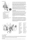
1. Output Shaft Oil Seal
2. Speedometer Driven Pinion
3. Output Shaft Bearing Shims
4. Intermediate Shaft
5. Intermediate Gear Thrust Washer
6. Intermediate Gear
7. Main Shaft Gar
8. Intermediate Gear Bearing
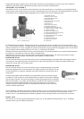
9. Output Shaft Clutch Gear
10. Output Clutch Shaft Pilot Bushing.
11. Companion Flange Assembly – Front
12. Output Clutch Shaft
13. Output Clutch Shaft Bearing
14. Output Clutch Shaft Bearing Snap Ring
15. Output Shaft Bearing Cap
16. Output Shaft Bearing Cone and Roller
17. Output Shaft Gear
18. Output Shaft Sliding Gear
19. Speedometer Drive Gear
20. Output Shaft
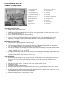
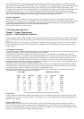
On hard surface and level roads, disengage the front axle by placing the transfer case shift lever in the forward position. See
Fig. 3 in GETTING STARTED. The right hand lever controls the gear ratio; low and high. The low gear can only be engaged
when the left hand lever is in the engaged (rear) position for front drive. Proper position for disengaging axles to use the power
take-off with the vehicle standing is shown as “N” in Fig. 3 in GETTING STARTED.
Both the transmission and the transfer case are precision built units. No external adjustments are possible and should attention
be necessary, it is advisable to consult your Willys-Overland Dealer.
IMPORTANT: Check the units at each lubrication to guard against lubricant leakage. For economy the capacity is small –
change the lubricant in accordance with instructions in GENERAL LUBRICATION.
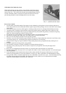
PROPELLER SHAFT
The drive from the transfer case to the front and rear axles is completed through two propeller shafts each equipped with two
universal joints. The splined slip joints at the transfer case end of each shaft allows for variations in distance between the
transfer case and the axles, due to spring action.
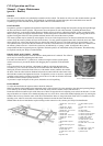
PROPELLER SHAFT
The drive from the transfer case to the front and rear axles is completed through two propeller
shafts each equipped with two universal joints. The splined slip joints at the transfer case end
of each shaft allows for variations in distance between the transfer case and the axles, due to
spring action.
Examine both propeller shafts periodically for foreign matter which may become wrapped
around them. Check for dents or a bent shaft and make sure that the universal joints attaching
bolts are tight at all times. The universal joints have needle type bearings and are so designed
that correct assembly is very simple. No hand fitting or special tools are required. The journal
trunnions and needle bearing assemblies are the only parts subject to wear, and when it
becomes necessary to replace these parts, the propeller shafts should be removed from the
vehicle to facilitate replacement.
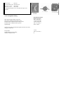
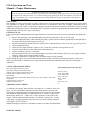
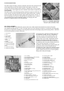
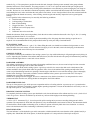
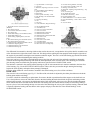
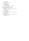
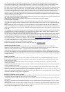
When reinstalling, note that the slip joints are marked with arrows, Fig. 24, at the spline and the sleeve yoke. Align the arrows
so the yokes of the universal joints at the front and rear of each shaft are in the same plane, when assembled, to avoid
vibration. The "U" type attaching bolt nuts should be tightened evenly with approximately the same pressure on each nut.
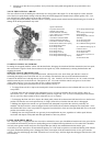
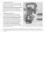
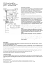
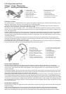
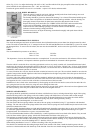
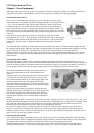
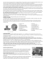
FRONT AXLE
The front axle is a live driving unit with hypoid drive gears, Fig. 26, and spherical steering knuckles, Fig. 25, containing
constant velocity type axle shaft universal joints.