


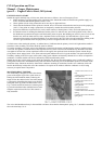

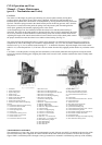

FUEL SYSTEM
The fuel system consists of the fuel tank lines, fuel pump, carburetor
and air cleaner. The most important maintenance attention is to keep
the system clean and free of water, also periodically inspect for leaks.
Should the vehicle be stored for an extended period, the fuel system
should be completely drained and the engine started and allowed to run
until the carburetor is emptied. This will avoid oxidation of the fuel,
resulting in the formation of gum in the units of the system.
Gum formation is similar to hard varnish and may cause trouble in the
fuel pump valves or the carburetor float valve may become stuck or the
filter screen blocked. Gum formation can be dissolved by acetone,
obtainable in most drug stores. In extreme cases, it will be necessary to
disassemble and clean the fuel system, however, often one pint of
acetone placed in the fuel tank with about one gallon of gasoline will
dissolve any deposits as it passes through the system with the gasoline.
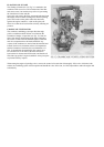
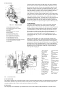
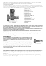
CARBURETOR
The Carter carburetor, Model W.O.-596S is a precision instrument
designed to deliver the proper fuel and air mixtures at all engine
speeds. Carburetor parts wear little; the chief cause of faulty carburetor
is blamed for poor engine performance when the trouble is elsewhere
(see EMERGENCY CARD). Do not disturb the carburetor until it is
proven that the trouble is not elsewhere. Should it be determined that
the carburetor is at fault consult your Willys-Overland Dealer.
The carburetor is provided with an external adjustment to secure
smooth engine idle. Fig. 14, No. 15. To set this adjustment, proceed
asa follows:
Make sure that the choke is in a fully open position Close the idle
adjustment by turning it to the right or in against the seat; then open it
one and one-quarter turns. Start the engine and run it until operating
temperature is obtained, then turn the adjustment in or out slightly until
the engine fires evenly. Open the throttle for a few seconds allowing
the engine to clean the manifold. Recheck the adjustment, then set the
throttle stop screw at an idle speed of 600 tpm. or approximately 6
miles per hour in high gear.
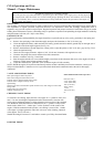
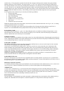
1. Pump Operating
Lever Assembly
2. Choke Valve
Assembly
3. Choke Shaft and
Lever Assembly
4. Metering Rod
Spring
5. Nozzle
6. Nozzle, Retaining
Plug
7. Metering Rod Disc
8. Neddle, Pin, Spring
and Seat Assembly
9. Float and Lever
Assembly
10. Low Speed Jet
Assembly
11. Idle Well Jet
12. Metering Rod Jet
and Gasket Assembly
13. Metering Rod
14. Nozzle Passage
Plug and Gasket
Assembly
15. Idle Adjustment
Screw
16. Idle Adjustment
Screw Spring
17. Idle Port Rivet
Spring
18. Throttle Valve
19. Pump Jet
20. Pump Jet Strainer
Nut
21. Pump Jet Strainer
22. Intake Ball Check
Assembly
23. Discharge Disc
Check Assembly
24. Pump Plunger
Spring
25. Pump Plunger and
Rod Assembly
26. Pump Arm Spring
27. Pump Connecting
Link
28. Pump Arm and
Collar Assembly
FIG. 14 CARBURETOR
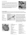
FUEL DIFFUSER
The engine is equipped with a fuel diffuser built as part of a thick insulting gasket which is installed between the carburetor
and the intake manifold. In operation the diffuser causes intense swirling of the fuel and air in the manifold. Under some
operating conditions this results in a drier and more satisfactory fuel mixture.
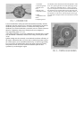
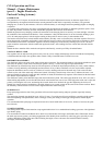
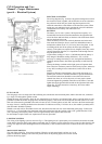
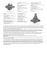
FUEL PUMP
The fuel pump is of the diaphragm type attached to the left side of the crankcase and operated from an eccentric on the