


CJ2A Operation and Care
Manual -- Proper Maintenance
(part 4 -- Electrical System)
ELECTRICAL SYSTEM
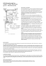
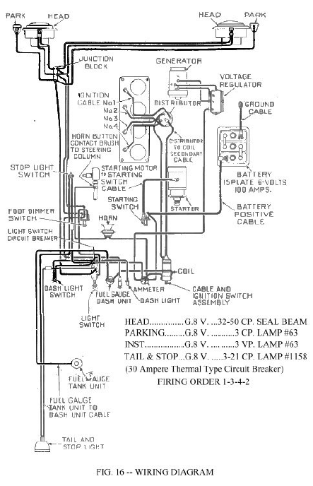
The wiring diagram (Fig. 16) shows the general arrangement of all of
the electrical circuits, together with all the units in correct relation to
the position in which they are found. Regular inspection of all
electrical connections avoids failures in the electrical system. When
tracing any one particular circuit, note that the wires have different
coloured tracers to identify each individual wire.
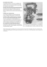
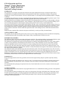
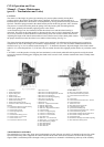
BATTERY
The battery is of 6-volt, 15-plate, 100-ampere hour capacity. It is
located under the hood on a bracket attached to the right hand side
rail of the frame and held firmly on the base with a hold-down frame
and two studs and wing nuts.
Check the battery once a week with a hydrometer and at the same
time check the electrolyte level in each cell; add distilled water to
maintain the solution level 5/8” (9.52 mm.) above the plates. Avoid
overfilling and do not fail to replace the filler caps and tighten
securely. If the plates are exposed for any length of time, they can be
seriously damaged, therefore, it is important to add enough water to
keep the plates covered.
A hydrometer reading of 1.285 to 1.300 indicates that the battery is
fully charged. Should the reading fall below 1.225, it will be
necessary to recharge the battery or else use lights and the battery
sparingly until the battery has had an opportunity to build itself up
again.
Coating the battery terminals with a light grease will protect them
from corrosion. The battery must be held securely in place, otherwise
it may shift, resulting in loose connections, broken cells or other
trouble.
Should a sufficiently charged battery fail to crank the engine, it is
probably due to loose or corroded terminals or ground connections.
The terminal connections should be removed and all corrosion
cleaned from them, as well as the posts, to insure proper contact.
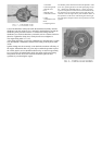
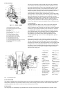
Clean and tighten the grounded connection on the frame. Clean and
tighten the engine ground cable located on the right hand side of the
engine Fig. 10. This connection is necessary, due to the rubber
engine mountings.
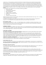
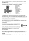
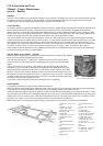
FUEL GAUGE
The fuel gauge circuit is composed of the indicating unit, mounted on the instrument panel, and the fuel tank unit, connected
by a single wire through the ignition switch.
Should the gauge fail to register, check all wire connections to be sure they are tight and clean; also be sure both units are well
grounded. If, after this check, the gauge does not indicate properly, remove the wire from the tank unit and connect it to a new
tank unit which must be grounded to the tank or frame for test. Turn the ignition switch “ON” and move the float arm through
its range of travel, watching the dash unit to determine if it indicates correctly. If it fails to do so, the trouble is probably in the
dash unit and it should be replaced.
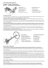
Should a new tank unit be unavailable for this test, disconnect the tank unit wire at the instrument panel gauge. Connect one
lead of a 6v., 1 CP test light to the instrument panel unit terminal and with the ignition switch “ON” ground the other. If the
unit is operating correctly the pointer will move approximately three-quarters across the dial.
Do not attempt to repair wither unit; replacement is the only procedure.
LIGHTING SYSTEM
The wiring of the lighting system is shown in Fig. 16. The lighting circuit is protected by an overload circuit breaker mounted
on the back of the main light switch and no replaceable fuse is required. It clicks off and on in the event of a short circuit in the
wiring. The upper and lower headlight beams are controlled by a foot switch located on the toe board at the left of the clutch
pedal.
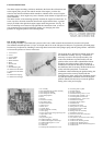
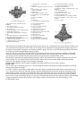
MAIN LIGHT SWITCH
The main light switch Fig. 18 has three positions. When the switch control knob is all the way in, all
lights are turned off. Pulling it out to the first position turns on the parking lights; all out to the second
position, the driving lights.