


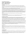
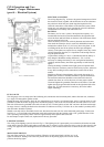
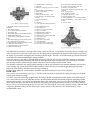
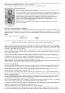
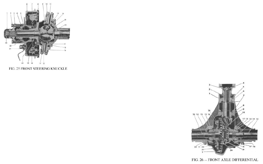
1. Cap, Wheel Hub -- Left or Right
2. Cap Screw
3. Shim Pack, Adjusting, Front Axle Universal
Joint
4. Cone and Rollers, Wheel Bearings
5. Spindle, Front Wheel
6. Brake Drum
7. Brake Cylinder Assembly -- Front
8. Plate, Backing, Front and Rear Brake
Assembly
9. Cup, King Pin Bearing
10. Nut
11. Pin, King
12. Cone and Rollers, King Pin Bearings
13. Oil Seal, Steering Knuckle, Assembly
14. Universal Joint Assembly, Front Axle
15. Bushing, Axle Shaft, Front
16. Shim Pack, Adjusting, King Pin Bearing -- Top
or Bottom
17. Pin, Lock, King Pin
18. Pin, Brake Shoe Anchor
19. Brake Shoe and Lining -- Front
20. Oil Seal Assembly, Hub
21. Wheel Hub Bolt Nut -- L.H. and R.H. Thread
22. Cup, Wheel Bearing -- Inner or Outer -- Front
and Rear
23. Nut, Axle Shaft
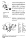
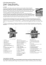
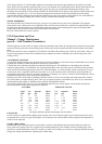
1. Hypoid Bevel Drive Gear and Pinion Set
(Matched)
2. Drive Pinion Oil Seal
3. Universal Joint End Yoke Assembly
4. Drive Pinion Nut
5. Pinion Shaft Bearing Cone and Rollers (Outer)
6. Pinion Shaft Bearing Cup
7. Pinion Bearing Adjusting Shims (Front and
Rear)
8. Drive Pinion Bearing Cone and Rollers (Rear)
9. Drive Pinion Bearing Cup (Rear)
10. Differential Bevel Pinion Mate Shaft Lock Pin
11. Differential Adjusting Shims
12. Differential Bearing Cone and Rollers.
13. Differential Bearing Cup
14. Oil Seal Differential End
15. Axle Shaft (Left)
16. Gear Cover Screw Lockwasher
17. Gear Cover Screw
18. Differential Bevel Side Gear
19. Differential Pinion Mate
20. Differential Bevel Pinion Mate Shaft
21. Gear Carrier Cover
22. Differential Case
23. Gear Carrier Cover Gasket
24. Axle Shaft (Right)
25. Hypoid Bevel Drive Gear Screw
26. Drive Gear Screw Locking Strap
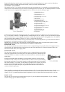
The differential is mounted in a housing similar to that used in the rear axle, except that the drive pinion shaft is toward the rear
of the front and to the right of the centre of the axle. This design allows placing the front propeller shaft along the right side of
the engine oil pan without reducing the road clearance under the engine. The axle is of the full floating type and the axle shafts
can be removed without dismantling the steering knuckles.
Once each year have your Willys-Overland Dealer remove the front axle universal joint and shaft assemblies to thoroughly
wash out the steering knuckle housings and check the shim adjustment of the universal joints. After checking, the universal
joint housings must be refilled with good quality lubricant as specified in the LUBRICATION section.
The lubricant is retained in the steering knuckle housings by felt oil seals mounted in twin retainers attached to the inner face
of the housings, Fig. 5 in the GETTING STARTED section. These seals also prevent dirt and grit entering the housings.
Inspect the seals regularly and replace them promptly if damaged.
Keep the spring loaded air vent or breather, mounted in the center housing cover, free of dirt at all times.
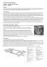
REAR AXLE
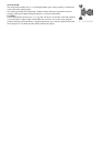
The rear axle is the semi-floating type, Fig. 27. End float of the axle shafts is adjusted by the shims placed between the brake
backing plate and the axle flange.
To remove a shaft for reshimming or replacement, first remove the hub cap and bend back the tongues on the shaft lock nut.
Use a wheel puller to remove the wheel hub. Remove the bolts holding the brake dust shield, the grease and bearing retainer
and the brake assembly. Also remove the shield and retainer. Pull out the shaft, using care not to lose the bearing adjustment
shims. Should the end of a broken shaft be inside the axle housing tube, the broken end can usually be removed by making a
loop in a piece of wire and working the loop over the end of the shaft using the wire to pull it from the housing. When the shaft
is replaced, adjust the bearing with the shims to allow proper end play of the shaft. See “Rear Wheel Bearings” in the
SUSPENSION section.