


required or provided with this governor, however this slack or lost motion is provided to cushion any slight irregularities in
governor control.
MAINTENANCE
Change the oil in the governor at each engine oil change, using the same grade oil used in the engine. Fill it to the level plug
opening slowly – do not overfill. Should any trouble occur which requires disassembly, consult your Willys-Overland Dealer.
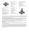
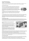
POWER TAKE-OFF WITH SHAFT AND BELT PULLEY
The complete power take-off consists of three assemblies; the shift unit (mounted on the transfer case), the shaft drive
assembly and the pulley drive assembly (mounted at the rear of the vehicle). The rear units are driven through the shaft
assembly by a propeller shaft and two universal joints.
The assembly, mounted at the rear of the vehicle, is designed to drive trailed equipment or operate belt driven machines. The
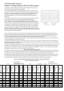
shaft and pulley speeds conform to SAE standards and are obtained at the maximum torque speed of the engine. For
information covering the power take-off shaft and pulley speeds, see the chart on the “Power Take-Off and Vehicle Speeds”
page.
FRONT UNIT OR SHIFT ASSEMBLY
This assembly, attached to the rear of the transfer case and operated from the transmission main shaft, provides a gear shift for
control of the power take-off. The shift assembly is lubricated from the transfer case and no attention is required other than the
regular lubrication of the transfer case.
Keep the attaching screws tight at all times. Always disengage the clutch when shifting the gear. When using the belt drive, do
not attempt the shift until the machine being driven has “coasted” to a stop.
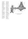
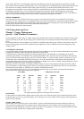
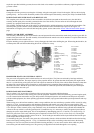
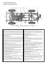
1. Fork and Rod
2. Ball
3. Lever
4. Nut
5. Spring
6. Button and Spring
7.Trunnion and Ball 8. Cup
9. Bearing
10. Snap Ring
11. Plate
12. Gasket
13. Retainer
14. Gasket 15. Gear
16. Oil Seal
17. Oil Seal
18. Oil Seal
19. Gear and Shaft
20. Cup
21. Cone and Ro
ller 22. Shims
23. Spacer
24. Shims
25. Shims
26. Pinion
27. Cone and Roller
28. Cup 29. Shaft
30. Gasket
31. Shims
32. Gasket
33. Gear
34. Shaft
35. Gasket 36. Washer
37. Oil Seal
38. Ball Bearing
39. Gear and Shaft
40. Spacer
41. Gasket
42.Sleeve
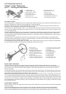
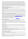
PROPELLER SHAFT AND UNIVERSAL JOINTS
The power take-off propeller shaft is tubular and has two universal joints. The joints are enclosed by housings and boots,
which contain the lubricant. The torque capacity of the propeller shaft is far greater than that developed by the engine and as
there is very little flexing of the joints, this unit will require no attention for the life of the vehicle under normal use other than
an inspection at each regular vehicle inspection, to guard against loose companion flange attaching screws or leakage of
lubricant at the boots. Should the power take-off be used often for continuous operation, disassemble the joints and repack
them with lubricant once each year.
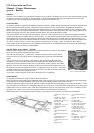
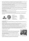
POWER TAKE-OFF SHAFT DRIVE
The six-splined 1 3/8” power take-off shaft provides a power output to operate trailed equipment.
Always use four wheel drive when towing power driven equipment. Selection of the most satisfactory governed engine speed,
as well as transmission and transfer case gear shift positions will depend upon the soil conditions and the power required to
pull the trailed equipment; also when operating agricultural machines, upon ground and machine speed requirements and crop
conditions.
When towing power driven farm machines, under average conditions, the most satisfactory operation will be secured by using
either No. 5 or No. 6 governor position with both the transmission and transfer case gears in the low range position. This
engine speed and gear combination provides a ground speed of from 4 to 4 ½ miles per hour and a power output shaft speed of
535 to 600 rpm. Under extremely heavy crop conditions it may be found that the machine being operated cannot handle the
volume of the crop which is cut at this ground speed. To handle the crop, it is necessary to reduce the ground speed without
changing the power output shaft speed. This is accomplished by interchanging gears No. 33 and No. 15 as shown in Fig. 35.
These two gears form a drive ratio within the power output unit of either 20 to 24 (5 to 6) or 24 to 20 (6 to 5). The original
factory assembly is made to provide a ratio of 20 to 24 – the 20-tooth gear assembled on the input shaft and the 24-tooth gear
on the output shaft as shown in Fig. 35.
To interchange the gears, first remove the power take-off assembly from the vehicle and drain the lubricant from the housing.
Remove the bearing retaining plate No. 11, Fig. 35. Bend back the lips of the nut locking washer and remove the bearing
retaining nut. The cover may then be removed with the bearing assembly. Use care not to lose the shims which are placed
between the gear hub and the bearing cone. The gear may be slipped from the shaft through the cover opening.