


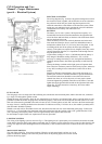
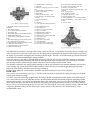
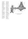
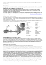
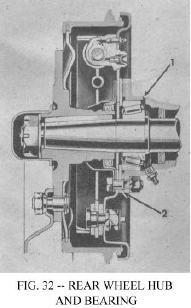
shims, Fig. 32, No. 2 to adjust the bearing with .001" to .003" end float which will be just perceptible when tested by hand. The
shims available for this adjustment are .003" - .005" and .030" thick.
Examine the grease retainer to be sure it is serviceable -- replace it if in doubt, and reassemble.
MAINTENANCE OF WHEEL BEARINGS
When the vehicle is used for road work, lubricate and adjust the front wheel bearings once each
year; if used in dusty field work, twice each year.
The bearings should be given more than casual cleaning. Use a clean stiff brush and suitable grease
solvent to remove all particles of old lubricant from the bearings and hubs. After the bearings are
thoroughly cleaned, inspect them for pitted races and rollers and check the hub oil seals.
Repack the bearing cones and rollers (see LUBRICATION SECTION) and reassemble in the
reverse order of dismantling. Adjust them as directed in the preceding paragraphs.
Lubricate the rear wheel bearings sparingly. Oil forced from the oil relief hole No. 1, Fig. 32,
indicates when the bearing is amply lubricated.
Should it be necessary to adjust the bearings, clean them thoroughly and repack them with the
recommended lubricant.
MOUNTING AND DISMOUNTING WHEELS
The wheel mounting nuts and studs on both left wheels have left hand threads to prevent them from being loosened by wheel
action. The studs are identified by an "L" stamped on the end. The left hand threaded nuts are identified by a groove cut around
the hexagonal faces. To remove the left wheels, the nuts must be turned RIGHT, and to remove the right wheels, turned to the
LEFT.
TIRES
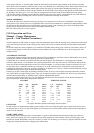
The recommended tire pressures are as follows:
6:00 x 16 Tires
7:00 x 15 Tires
28-30 lbs.
20-21 lbs.
The importance of correct tire inflation cannot be overemphasized. To secure the maximum tire life and most efficient vehicle
operation, it is imperative that these pressures be maintained for all normal vehicle operations.
Then the vehicle is used with driver only doing agricultural work on very sandy or muddy soil, increased flotation and wheel
traction may be secured by decreasing the pressure of the 6:00 x 16 tire to 18 to 20 lbs., and the 7:00 x 15 tire to 14 lbs. Should
unusual operating conditions require this reduction in pressure, use care that the tires are inflated to the recommended pressure
immediately when normal operation is resumed.
To secure maximum tire wear, the wheels should be switched at least twice each year. The rear wheels should be moved to the
opposite front positions and the right front wheel moved straight back to the right rear position. Place the spare on the left rear
and use the left front as a spare.
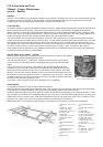
To remove a tire from a drop centre rim, first deflate completely and then force the tire away from the rim throughout the
entire circumference until the bead falls into the centre of the wheel rim, then with a heavy screw driver or tire removing tool,
used opposite the valve, remove one side of the tire at a time and remove the inner tube.
Installation of a tire is made in the same manner by first dropping one side of the tire into the centre of the rim and with a tire
tool, spring the bead over the wheel rim, using care not to damage the inner tube.
When mounting the wheel, alternately tighten opposite stud nuts to prevent wheel wobble. After nuts have been tightened with
the wheel jacked up, lower the jack so wheel rests on the floor and retighten the nuts.
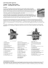
SPRINGS AND SHACKLES
The springs should be periodically examined for broken or shifted leaves, loose or missing rebound clips, angle of the spring
shackles and the position of the springs on the axle saddles. Springs with shifted leaves to not have their normal strength.
Missing rebound clips may permit the leaves to fan out or break on rebound. Broken leaves may make the vehicle hard to
handle or permit the axle to shift out of line. Weakened springs may break causing difficulty steering.
The front springs are interchangeable, as are the two rear.
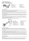
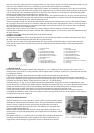
The front ends of the front springs and the rear ends of the rear springs are shackled, using "U" type shackles with threaded
bushings. The rear ends of the front springs and the front ends of the rear springs are bronze bushed and pivoted on bolts in the
shackles mounted on the frame.
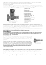
The spring shackle threaded bushings use right and left hand threads, depending upon where they are to be used. Six bushings
are used with right hand threads and two with left hand threads. For identification the right hand threaded type have plain
hexagonal heads. The left hand have a groove cut around the heads.
The two left hand threaded shackles can be identified by a small forged boss on the lower shank of the shackle. They are used
at the left front and the right rear springs with the left hand threaded end down at the spring eyes.
The bushings are anchored solidly in the frame brackets and spring eyes and the oscillation taken between the threads of the
"U" shackle and the inner threads of the bushings. The lubrication of the shackle bushings is very important and should not be
neglected, or excessive wear of the bushings and "U" shackles will occur.
When making installation of a new "U" shackle or bushing, follow the procedure below:
The shackles are installed with the bushing hexagon heads to the outside of the frame. Install the shackle grease seal and
retainer over the threaded end of the shackle up to the shoulder. Insert the new shackle through the frame bracket and the eye