Should it be necessary to install a new light switch, refer to the wiring diagram, which indicates the
correct wires to install on the several terminals. To remove the switch, loosen the set screw in the side
of the switch control knob and remove the knob by unscrewing. The retaining nut may then be removed
and the switch removed through the rear of the instrument panel.
STOPLIGHT SWITCH
The stoplight switch is of the diaphragm type and is located in the front end of the brake master cylinder. When the switch
becomes inoperative, it is necessary to install a new one.
HEADLAMP AIMING
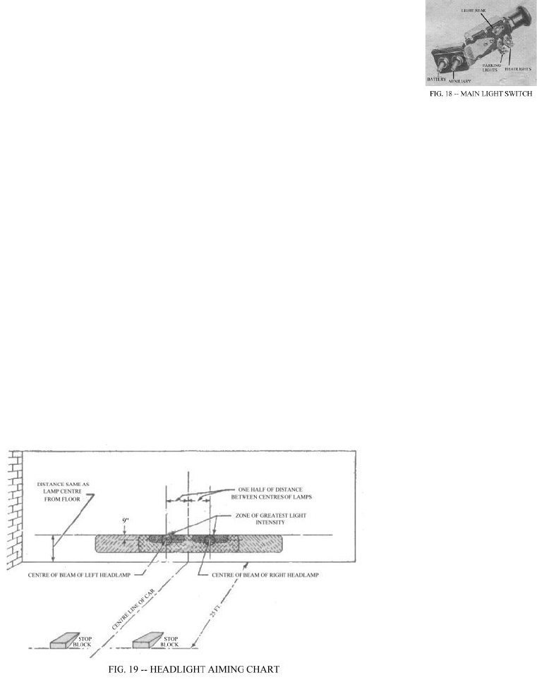
Headlamps may be aimed correctly by using an aiming screen or wall, Fig. 19, providing a clear, level space of 25 feet from
the front of the headlights to the screen or wall is available.
The screen should be made of light coloured material and should have a black centre line for use in centering the screen with
the vehicle. The screen should also have two black vertical lines, one on each side of the centre line at a distance equal to the
lamp centres.
Place the vehicle on the floor with the tires inflated to the recommended pressure for highway use. Set the vehicle 25 feet from
the front of the screen or wall so that the centre line of the vehicle is in line with the centre line on the screen. To position the
vehicle, stand at the rear and sight through the windshield down across the cowl and hood. Measure from the floor to the centre
of the headlamp and mark a horizontal line on the screen 3 inches less. Turn on the headlamp upper beam, cover one lamp and
check the location of the beam on the screen. The centre of the “hot spot” should be centred on the intersection of the vertical
and horizontal lines. If the aim is incorrect, remove the headlamp door screw and remove the door, then adjust the two screws
in the mounting ring and move the headlamp unit until the beam is correctly aimed, then tighten. Cover the headlamp aimed
and adjust the other in the same manner.


