CJ2A Operation and Care
Manual -- Proper Maintenance
(part 2 -- Engine Fails to Start, Oil System)
ENGINE FAILS TO START
Should the engine suddenly stop or fail to start, check the cause as follows. Also see Emergency Chart.
• Make sure there is gasoline getting to the carburetor (Note: Should the trouble be traced to the gasoline supply see
FUEL SYSTEM) and that the ignition switch is “ON”.
• Check ignition circuit wiring connections to be sure they are tight and clean.
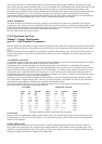
• Check that the distributor breaker points are smooth, have a flat contact with each other and are set to the proper gap
(.020”). If the points are rough, replace them or temporarily smooth them with a breaker point file.
• Inspect the distributor cap and rotor for cracks, carbon runners or burned places. If they are found replace the part.
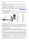
• See that the current is reaching the distributor breaker points. To make this test, turn on the ignition switch, remove
the distributor cap and turn the engine until the breaker points are open, then holding one end of a piece of wire on the
breaker arm, strike the other end on a clean, unpainted surface of the engine. No flash indicates a poor or open
connection between the switch and distributor or an open circuit in the coil. If the wire and connections leading to the
coil are in good condition, then an open primary in the coil is apparent and a new coil will be necessary.
If a flash occurs when testing the primary, as outlined above, it indicates that the primary circuit is all right and the trouble is
elsewhere so the secondary coil circuit should be tested as follows:
To test the secondary coil circuit, remove the distributor cap and turn the engine until the breaker points are making contact.
Turn “ON” the ignition switch and remove the high tension wire (center wire) from the distributor cap. Hold this wire about
one-eighth of an inch from a clean, unpainted surface of the engine, then open and close the breaker points with the finger,
giving them a short, snappy break. A fat, flame-coloured spark indicates the coil is in good condition. No spark indicates the
secondary winding of the coil is open, while a thin, stringy spark indicates an internally shorted coil or a loose or inoperative
condenser. Condenser trouble will also be indicated by badly burned breaker points.
Should the test show a thin, stringy spark, check the condenser first. Be sure that the mounting screw is tight and is making a
good ground connection to the distributor body and also that the connecting wire to the distributor points is not broken or the
connection loose. Should no trouble be found in the condenser mounting or connection, install a new condenser which will
localize the difficulty in either the coil or the condenser. No repairs can be made to either the condenser or coil, it being
necessary to replace them if inoperative.
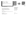
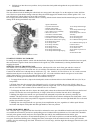
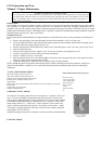
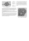
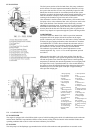
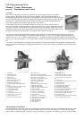
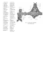
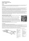
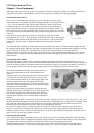
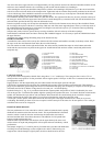
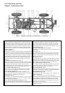
MANIFOLD HEAT CONTROL
The manifolding is designed to utilize the exhaust
gasses of the engine to provide a quick means of
heating the inlet manifold, thereby reducing the
length of time the choke must be used after starting
a cold engine and making the engine more flexible
during the warm up period. The heat control valve,
Fig. 9, which controls the amount of exhaust gasses
by-passed around the intake manifold insures more
complete vaporization of the fuel. This control is
fully automatic.
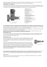
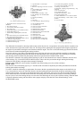
1. Heat Control Valve Lever
Key
2. Heat Control Valve Lever
Clamp Bolt Nut
3. Heat Control Valve Shaft
4. Heat Control Valve Lever
Clamp Screw
5. Heat Control Valve Bi-Metal
Spring Washer
6. Heat Control Valve
Counterweight Lever
7. Heat Control Valve Bi-Metal
Spring
8. Heat Control Valve Bi-Metal
Spring Stop
The valve shaft should turn freely in the manifold at all times. Note that the thermoplastic spring, No. 7, should be assembled
above the metal stop, No. 8.