


CJ2A Operation and Care
Manual -- Proper Maintenance
(part 7 -- Steering and Suspension)
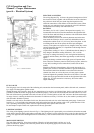
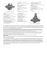
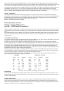
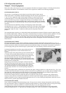
1. Tie Rod - Right
2. Tie Rod Socket - Right
3. Knuckle and Arm - Right
4. Steering Bell Crank
5. Steering Connecting Rod
6. Steering Gear Arm
7. Steering Gear Arm Assembly
8. Knuckle and Arm - Left
9. Tie Rod Socket - Left
10. Tie Rod - Left
11. Socket Assembly
12. Steering Bell Crank Pin
13. Steering Bell Crank Cotter Pin
14. Steering Bell Crank Shaft
STEERING SYSTEM
The “Steering System” is illustrated in Fig. 30. It requires little attention other than proper lubrication and maintaining correct
alignment. Alignment may be thrown out by striking curbs or other obstructions.
Looseness in the steering system will also affect alignment. It is impossible to satisfactorily align front wheel without first
adjusting the various connections, including the front wheel bearings.
The correct toe-in of the front wheels is 3/64” – 3/32” which must be accurately measured for satisfactory front tire wear and
steering. The best method of checking wheel alignment is by the use of the wheel alignment device, which is available in most
every well equipped shop.
Periodic inspection and tightening of the steering parts will aid greatly in maintaining alignment. Keep the steering connection
rod and tie rod ball joints snug; they must operate freely without lost motion. Keep the steering gear arm No. 6 tight on the
lever shaft and the steering housing bracket tight on the frame. For adjustment of the front wheel bearings see the next section,
“Front Wheel Bearings”.
The bell crank No. 4 is mounted on the frame front cross tube and swivels on two needle bearings. The mounting shaft is
removable from the frame bracket by driving out a tapered locking pin. The bell crank tie-rod ball is replaceable. Should the
bell crank become bent or damaged, install a new part.
Do not tighten the steering gear to dampen out steering trouble. Should trouble develop, consult your Willys-Overland Dealer,
as he has a definite procedure for the inspection and adjustment of the steering system.
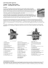
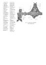
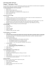
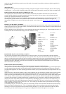
1. Housing Oil Seal
2. Lever Shaft Assembly
3. Housing Oil Filler Plug
4. Steering Column Clamp Assembly
5. Cam & Wheel Tube Assembly
6. Steering Column Oil Hole Cover
7. Horn Wire Contact Brush Assembly
8. Steering Wheel
9. Steering Column Bearing Spring
10. Steering Column Bearing Spring
11. Steering Column Bearing Assembly
12. Steering Column & Bearing Assembly
13. Steering Wheel & Horn Button Nut
14. Horn Button
15. Horn Button Spring
16. Horn Button Spring Cup
17. Side Adjusting Screw
18. Housing Assembly
19. Cam Bearing Balls
20. Steering Gear Arm
21. Housing Bushing - Inner
22. Housing Bushing - Oute
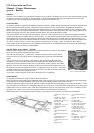
FRONT WHEEL BEARINGS
The front wheels are mounted on two opposed tapered roll bearings. These bearings are adjustable for wear and their
satisfactory operation and long life depends upon periodic attention and correct lubrication. Loose front wheel bearings may
cause excessive wear and will affect front wheel alignment. If the bearing adjustment is too tight, the rollers may break or
become overheated.
To check the adjustment, first raise the front of the vehicle so that the tires clear the floor. Check the brakes to be sure they are
free and fully released. With the hands, check sidewise shake of the wheel. If the bearings are correctly adjusted, shake of the
wheel will be just perceptible and the wheel will turn freely with no drag.
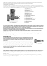
Should the test indicate that adjustment is necessary, remove the hub cap axle shaft nut, washer, driving flange and shims. See
Fig. 25. Wheel bearing adjustment will then be accessible. Bend the lip of the nut locking washer so that the adjustment lock
nut and washer can be removed. Rotate the wheel and tighten the adjusting nut until the wheel binds slightly. Then back off the
nut 1/6 turn, or more if necessary, making sure the wheel turns freely without sidewise shake. Replace the locking washer and
lock nut and bend over the locking washer lip. Check the adjustment and reassemble the driving flange, nut and hub cap, being
sure to replace the shims.
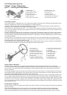
REAR WHEEL BEARINGS
Each rear wheel is carried on a single tapered roller bearing which is adjusted by shims placed between the brake backing plate
and the axle flange.
Check wheel bearing adjustment in the same manner as the front wheel. Should the check determine that adjustment is
required, remove the hub cap; remove the cotter pin, the axle shaft nut and use a wheel puller to remove the wheel hub.
Remove the bolts holding the brake dust shield, the grease and bearing retainer and the brake assembly. Remove or install