


14
DATE OF ISSUE: SEPTEMBER 1997
XK8 Range 1998User Instructions
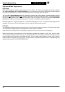
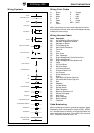
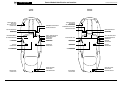
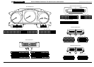
Harness Component Numbers
Connectors
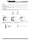
HARNESS CODE + CONNECTOR NUMBER + PIN NUMBER
EXAMPLE: FC7-24 (pin number is separated by a dash)
Where the pin number differs from LHD to RHD, the connector number will be further identified by (LHD) or (RHD).
FC7-24 FC7-24 (LHD)
FC7-15 (RHD)
RHS3 RHS3
BT29
BT29-1 BT29-2
AC20
3
1
5
2
4
AC20
8
6
10
7
9
Harness code
Pin number
Connector number
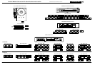
Splices
HARNESS CODE + S (SPLICE) + SPLICE NUMBER
EXAMPLE: RHS3 (no dash is used)
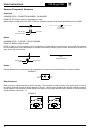
NOTE: In order to avoid unnecessary circuit complication, multiple splices (more than two wires) within components,
in wires leading from input components to multiple circuits and in harness ‘ground’ sides, are simplified so as not to
show wires from other circuits.
Harness code
Splice
Splice number
SIMPLIFIED SPLICE
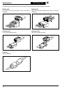
Diodes
Harness diodes occur at connectors and are depicted as components and identified by a connector number.
EXAMPLE:
Relay Connectors
Relay connector numbers are shown within the relay. The connector number is shown in the upper portion of the re-
lay; the pin (terminal) number is shown adjacent to the pin. Certain relays are paired and share a modular connector.
In this instance, the connector number remains the same for both relays while the pin numbers of the second relay
are identified by numbers 6 – 10.
EXAMPLE: