


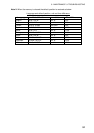

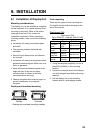


9. INSTALLATION
55
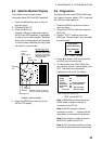
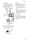
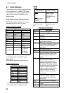
9.3 Wiring
The illustration below shows where to
connect cables on the rear of the display unit.
Please review the INSTALLATION
GUIDELINES at the front of this manual
before wiring the equipment.
Black
Red
(12-24 VDC)
Ground
1A Fuse
(+/- line)
ANTENNA UNIT
GPA-017
(For GP-32)
+
-
POWER
DISPLAY UNIT
GP-32 OR GP-37
ANTENNA UNIT
GPA-019
(For GP-37)
OR
With 10 m
cable
MJ-A7SPF0009-020,
2 m
*
* = Cut unused cores
and tape individually.
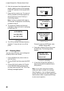
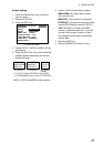
Wiring
Note: The fuse holder contains a spring that
fixes the fuse. To prevent detachment of the
spring, which would cause loss of power, tie
the line as shown below.
Fuse Holder
+ Line (Red)
- Line (Black)
Fix here.
How to fix spring in fuse holder
Grounding
The display unit contains a CPU. While it is
operating, it radiates noise, which can
interfere with radio equipment. Ground the
unit as follows to prevent interference:
•
The ground wire for the display unit should
be 1.25sq or larger and as short as
possible.
•
The signal ground and frame ground are
separated, however the power line is not
isolated. Therefore, do not connect the
signal ground to the frame ground when
connecting other equipment to a positive
ground battery.
External equipment
The power supply port is commonly used for
connection of external equipment such as a
radar. Refer to the interconnection diagram
on page S-1 or S-2 for connection of external
equipment.