


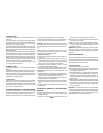
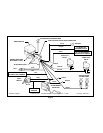
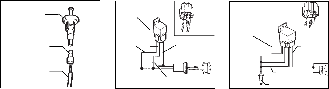
PIN SWITCH
CONNECT WHITE w/BLACK STRIPEWIRE
TO OTHERSIDE OF STARTWIRE
ORANGE WIRE-SPLICE TO
ORANGE WIREFROM
SIREN MODULE HARNESS
CONNECT BLACK
TO ONE SIDEOF
THE START WIRE
RED WIRE-SPLICE TO
THE IGNITION WIRE
WHITE/BLACK
+12 VOLTCONSTANT FUSED WIRE
BLACK-SPLICE
TO PARKING
LIGHT WIRE
ORANGE-SPLICE TO
YELLOW WIRE FROM
SIREN HARNESS
RED
MALE BULLET
TERMINAL
GREEN WIRE
Page 5
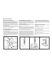
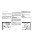
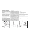
9. Connecting the Starter Disable Relay
IMPORTANT!Therelayhasbeenshippedwith(1)BLACKwireloose.
Whenusingtherelaytodisablethestarter,loadtheBLACKwireintothe
relayconnector inthelocationshown inthediagram.
9a. Connect the ORANGE wire from the relay harness to the
ORANGE wire from themain harness. Be sure toinsulate this
splicewith electricaltape.
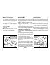
9b.Gainaccesstothewirescomingfromtheignitionswitch.Connect
theREDwirefromtherelayharnesstothewirefromtheignition
switch thatshows+ 12volts onthe logicprobewhen thekey is
switchedtothe“ONorRUN“and“START“positions,andshows
0voltswhen thekeyisswitchedto the“ OFF“position.Besure
toinsulate thisconnectionwith electricaltape.
9c.Locatethe wirecoming fromtheignitionswitchthat shows+ 12
volts onthelogic probewhen thestartermotor iscranking,and
shows 0 volts when the key is switched to the “ OFF “,
“ACCESSORY“,and“ONorRUN“positions.Cutthiswireand
try to start the vehicle to verify that the starter motor will not
engage.
ConnecttheWHITEw/BLACKstripewirefromtherelayharnesstoone
sideofthecutstarterwire,andconnecttheBLACKwiretotheotherside
of thecut wire.
CAUTION!Be surethesewires aresecurelyconnected, andproperly
insulated. Ifthis connection separates,the vehiclewill not start,even
whenusing theignitionkey.
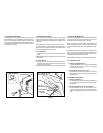
8. Connecting the DARK GREEN wire
Trim the DARK GREEN wire to the proper length, strip 1/4 “ of the
insulation,andcrimponeofthemalebulletterminalsprovidedontothe
endofthewire.Plugthebulletterminalontothereceptacleatthebottom
of thehoodpin switch.
Ifyouhaveinstalledatrunkswitch,youshouldhavealreadyroutedthe
DARKGREENextensionwiretotherearofthevehicle.Crimptheother
bulletterminalontotheendoftheextension,andplugitontothebottom
ofthetrunkpinswitch.You willalsoneed tosplicethe otherendof the
DARKGREENextensionwiretotheDARKGREENwirefromthemain
harness,and insulatethesplice withelectricaltape.
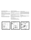
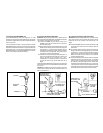
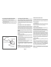
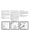
10. Connecting the Parking Light Flasher Relay
IMPORTANT!Therelayhasbeenshippedwith(1)BLACKwireloose.
When using the relay to flash the vehicle’s parking lights, load the
BLACK wire into the relay connector in the location shown in the
diagram.
10a.ConnecttheORANGEwirefromtherelayharnesstotheYELLOW
wire from the main harness. Besure to insulate this splice with
electricaltape.
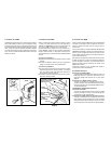
10b.Gainaccesstothewirescomingfrom theback ofoneof thefront
parkinglampsockets.Switchtheparkinglightson,andlocatethe
wirethat shows+12volts onthelogic probe.Switchtheparking
lightsoff,andverifythatthiswirenowshows0volts.Connectthe
BLACK wire from the relay socketto this wire, and insulate the
connectionwithelectrical tape.
10c.ConnectboththeREDwirefrom therelaysocket andtheWHITE
w/BLACK stripewire fromtherelay sockettoa+12voltbattery
fusedwire(minimum15Ampfuse)inthevehicle.Thesewirescan
be connected to the positive battery terminal, however when
connectingthemtothepositivebatteryterminal,youmustaddan
inlinefuseofatleast15Amps.Connectonesideofthefusetothe
positivebatteryterminal,andtheothersideofthefusetotheRED
and WHITEw/BLACK stripewires fromthe relayconnector.