


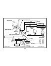
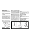
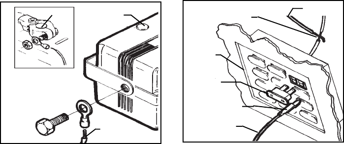
NEGATIVE TERMINAL
BLACK WIRE
SIREN MODULE
RADIO FUSE,
WIPER FUSES, ETC.
SPLICE INTOWIRE AND WRAP
WITH ELECTRICAL TAPE
FUSE BOX
FUSE CLIP TERMINAL
(NOT INCLUDED)
WHITE WIRE
A
B
WHITE WIRE
Page 4
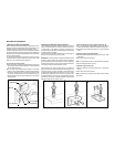
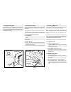
3. Connecting the BLACK Wire
ThelargerBLACKwire(notthethinblackantennawire),shouldhave
beenconnectedtogroundduringthesirenmodulemountingprocedure.
Ifyouwereunsureofthegroundreliabilityofthesirenmodulemounting
bracket,youcanconnecttheeyeletontheendoftheBLACKwiretoany
nonpaintedboltonthefirewallorfender,whichisthreadeddirectlyinto
a metalsurfaceof thevehicle.
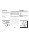
4. Connecting the WHITE wire
Locateafuseinthevehicle’sfuseboxthatshows+12voltsonthelogic
probewhentheignitionkeyisswitchedtothe“ON“or“RUN“position,
andshows0voltswhenthekeyisswitchedtothe“OFF“position(radio
or wiperfuse ).
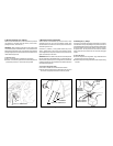
After youhavelocated asuitable fuse,switch theignitionkey tothe
“ON“position,removethefuse,andprobethecontactswherethefuse
plugsinto.Oneofthecontactswillnotshow12voltsonthelogicprobe;
this iswherethe WHITEwirewill beconnected.
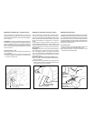
Connection Method A;
A. Locate the wire coming from thisfuse terminal atthe backof the
fusebox.
B.SplicetheWHITEwirefromtheharnesstothiswire,andinsulatewith
electricaltape.
Connection Method B;
A.“Fuseclip“terminals,whichwillpluginwiththecontactsofthefuse,
areavailable atmostelectronicsstores. Thismethodofconnection
maybe easierinsome vehicles.
B.Refertothespecificinstructionsincludedwiththefuseclipterminals.
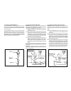
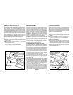
5. Connecting the BROWN wire
ContinuetoroutetheBROWNwire(alongwiththeDARKGREENwire
for connectionto thetrunk pinswitch )to theback ofthe vehicle,and
removethe panelstogain exposuretothe reverselights.
Switch the ignitionkey to the “ON “ position (DO NOT START THE
VEHICLE), settheparking brake,andmove thegearshift selectorto
reverse.Movetothebackofthevehicle,andverifythatthebackuplights
areon.
Probethewiresgoingtothebackuplightbulb,andlocatethewirethat
shows+ 12voltson thelogicprobe.Move thegearshiftselectorback
to theparkposition, andverifythat thissame wirenowshows 0volts.
Thisis wherethe BROWNwirewill beconnected.
Splice theBROWNwire tothiswire, andinsulate withelectricaltape.
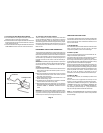
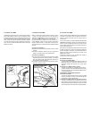
6. Connecting the L.E.D.
6a. Connectingthe DARK BLUEwire
ConnecttheDARKBLUEwirefromthemainharnesstotheBLUE
wire from the dash mounted L.E.D. Be sure to insulate this
connectionwithelectrical tape.
6b. Connecting theRED wire from the L.E.D.
Splice theRedwire fromthedash mountedL.E.D. tothelarger
REDwire fromthemain harness.Besure toinsulatethis splice
withelectrical tape.
7. Connecting the Valet Switch
7a. Connecting theGRAY wire
ConnecttheGRAYwirefromthemainharnesstotheGRAYwire
from the Valet Switch. Besure to insulate this connection with
electricaltape.
7b. Connecting theBLACK wire fromthe Valet Switch
Connect the BLACK wire from the Valet Switch to a solid,
grounded, metalpart ofthe vehicle.It canbe connectedto any
metal,non-paintedboltthatscrewsintotheinnerframeinthekick
panel.