


WIRING THE SYSTEM
Making the connections to the vehicle, as described in this wiring
section,maybebeyondthetechnicalabilitiesoftheaverageconsumer.
If you have any questions with the wiring procedures, please call a
qualifiedautomotivetechnician,orcallthe AUDIOVOXHOTLINE at1
-800-225-6074.Priortomakinganyconnections,a12Voltlogicprobe
shouldbe usedtoconfirmthe properconnectionpoint.
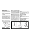
IMPORTANT!The9pinwhiteconnectorontheendofthemainharness
that plugs into the siren control module should remain disconnected
duringthewiringportionoftheinstallation.Leavingthisdisconnectedwill
ensurethatthekeychaintransmittersareproperlyprogrammedlaterin
theinstallation.
1. Routing The Wiring Harness
TheDARKBLUE,GRAY,ORANGE,BROWN,andWHITEwiresmust
beroutedthroughthe firewall,andinto thepassengercompartment of
thevehicle.
In most cases, the RED wire will also be routed into the passenger
compartment,tothecourtesylightfuse.Beforeproceedingwiththewire
routing, verify the location of the courtesy light fuse, as a small
percentageofvehicleslocatethisfuseintheenginecompartment,and
inthesecases,itwillnotbenecessarytoroutetheREDwirethroughthe
firewall.
Ifyouhaveinstalledapinswitchintothetrunk,youwillalsoneedtoroute
the DARK GREEN extension wire through the firewall, and to the
previouslyinstalled trunkpinswitch.
After confirming these component locations, route the DARK BLUE,
WHITE,GREY andREDwirestowardstheirconnectionpoints.Caution
should be used when routing wires. Keep wires away from all hot
surfaces,andanymovingpartsofthevehicle(radiatorfans,accelerator
orbrake pedallinkage, etc.).
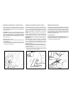
When routing wires through the firewall, be sure to pass the wires
through an existing rubber grommet. Failure to do this can result in
damagetowiresfromsharpmetaledges,andaneventualfailureofthe
security system.
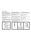
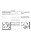
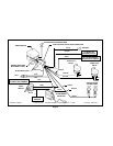
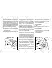
2. Connecting the RED Wire
Locatethecourtesylampfuse.Bothsidesofthefusewillindicate +12
Voltsonthelogicprobewhilethefuse ispluggedin.Remove thefuse,
and testthe contactsthat thefuse plugsinto. Oneof thecontactswill
notindicate +12Volts. Thisiswhere theREDwire willbeconnected.
Connection Method A;
A. Locate the wire coming from this fuse terminal at the backof the
fusebox.
B.SplicetheREDwire fromtheharnesstothiswire,andinsulate with
electricaltape.
Connection Method B;
A.“Fuseclip“terminals,whichwillpluginwiththecontactsofthefuse,
areavailable atmostelectronicsstores. Thismethodofconnection
maybe easierinsome vehicles.
B.Refertothespecificinstructionsincludedwiththefuseclipterminals.
Page 3
COURTESY
LIGHT FUSE
A
SPLICE INTOWIRE AND WRAP
WITH ELECTRICAL TAPE
B
FUSE BOX
FUSE CLIP TERMINAL
(NOT INCLUDED)
RED WIRE
RED WIRE
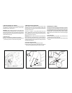
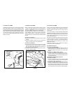
GLASS BREAK
DETECTOR
ADJUSTMENT ACCESS
MOUNT UNDER DASHUSING
SCREWS ORTWIST TIES
OPTIONAL - USEDOUBLE SIDED
ADHESIVE FOR MOUNTING
UNDERSIDE OF DASHON
BRACE OR PANEL
MICROPHONE
SCREW
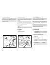
6. Mounting the Glass Break Detector
The glass break detector module should be mounted behind the
dashboard, in an area that will allow the extension cable from the
microphonetobepluggedin.Themicrophoneshouldbemountedonthe
lower dash lip, pointing towardthe rear of the vehicle. Mounting the
microphonetohardplasticpanelsorplasticairconditioningductsisnot
recommended, as normal expansionand contraction of plastics may
causeenoughnoisetocreateafalsetrigger.Youshouldalsomountthe
microphone below eye level, as the red L.E.D. willflicker onand off
whenevera sharpnoiseisdetected.
To mount these components;
A.Usethescrewsorwiretiestomounttheglassbreakmodulebehind
thedashboard.
B. Mount the microphone using the enclosed screw, or an optional
doublesidedadhesivepad.
C.Plugthemicrophonecableintotheglassbreakmodule,andsecure
thecable alongit’spath usingwireties.