


ATCA-C110/1G Installation and Use Manual
Chapter 5 Controls, Indicators and Connector Pin Assignments
64
REVIEW COPY
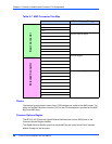
Zone 2 Connectors
Zone 2 contains four connectors: J20, J21, J22 and J23 (see Figure 5-3 on page 62) carrying
the following types of signals:
■ Telecom clock signals (CLKx_)
■ Base interface signals (BASE_)
■ Fabric channel interfaces (FAB_)
Some of the pins provided by J20, J21 and J23 are defined as optional in the ATCA specification
and are unused.on the blade. If the ATCA specification defines these signals as input signals,
they are terminated on the blade and marked as “TERM_” in the following pinouts.
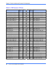
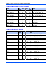
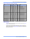
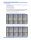
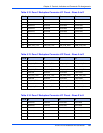
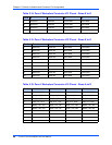
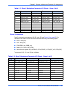
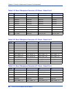
The pinouts for J20, J21, J22 and J23 are given below:
Table 5-10. Zone 2 Backplane Connector J20 Pinout - Rows A to D
Pin # A B C D
1 ATCA_CLK1A+ ATCA_CLK1A- ATCA_CLK1B+ ATCA_CLK1B-
2 XAUI_UP_TX3+ XAUI_UP_TX3- XAUI_UP_RX3+ XAUI_UP_RX3-
3 XAUI_UP_TX1+ XAUI_UP_TX1- XAUI_UP_RX1+ XAUI_UP_RX1-
4 FEC_UP_TX0+ FEC_UP_TX0- FEC_UP_RX0+ FEC_UP_RX0-
5 Reserved Reserved Terminated Terminated
6 Reserved Reserved Terminated Terminated
7 Reserved Reserved Terminated Terminated
8 Reserved Reserved Terminated Terminated
9 Reserved Reserved Terminated Terminated
10 Reserved Reserved Terminated Terminated
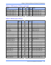
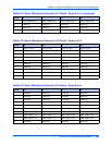
Table 5-11. Zone 2 Backplane Connector J20 Pinout - Rows E to H
Pin # E F G H
1 ATCA_CLK2A+ ATCA_CLK2A- ATCA_CLK2B+ ATCA_CLK2B-
2 ATCA_CLK3A+ ATCA_CLK3A- ATCA_CLK3B+ ATCA_CLK3B-
3 XAUI_UP_TX2+ XAUI_UP_TX2- XAUI_UP_RX2+ XAUI_UP_RX2-
4 XAUI_UP_TX4+ XAUI_UP_TX4- XAUI_UP_RX4+ XAUI_UP_RX4-
5 Reserved Reserved Terminated Terminated
6 Reserved Reserved Terminated Terminated
7 Reserved Reserved Terminated Terminated
8 Reserved Reserved Terminated Terminated
9 Reserved Reserved Terminated Terminated
10 Reserved Reserved Terminated Terminated