


Chapter 5 Controls, Indicators and Connector Pin Assignments
ATCA-C110/1G Installation and Use Manual
59
REVIEW COPY
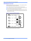
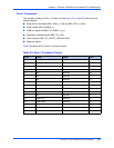
AMC Connectors
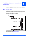
The AMC modules are connected to the carrier board via the AMC connectors. See Figure 5-2
on page 52 for AMC connector locations.
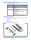
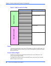
The AMC Connector has distinct regions for interfacing various interfaces on the AMC Card.
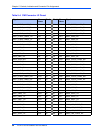
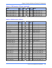
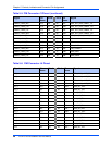
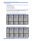
The port mapping of the AMC on the ATCA-C110/1G is shown in Table 5-7, followed by a brief
description of each mapped region. Table 5-8 on page 61 describes each port mapping of the
AMC Card on ATCA-C110/1G.
V12 S10+ 19 55 S28+ XAUI_UP_RX3+
V12 S10- 20
56 S28- XAUI_UP_RX3-
V12 S11+ 21
57 S29+ RTM_GBE_PORT0_TX+
VCC S11- 22
58 S29- RTM_GBE_PORT0_TX-
VCC S12+ 23
59 S30+ RTM_GBE_PORT0_RX+
V3_3_MGMT S12- 24
60 S30- RTM_GBE_PORT0_RX-
RTM_XAUI_LANE0_TX+ S13+ 25
61 S31+ RTM_GBE_PORT1_TX+
RTM_XAUI_LANE0_TX- S13- 26
62 S31- RTM_GBE_PORT1_TX-
RTM_XAUI_LANE0_RX+ S14+ 27
63 S32+ RTM_GBE_PORT1_RX+
RTM_XAUI_LANE0_RX- S14- 28
64 S32- RTM_GBE_PORT1_RX-
RTM_XAUI_LANE1_TX+ S15+ 29
65 S33+ RTM_GBE_PORT2_TX+
RTM_XAUI_LANE1_TX- S15- 30
66 S33- RTM_GBE_PORT2_TX-
RTM_XAUI_LANE1_RX+ S16+ 31
67 S34+ RTM_GBE_PORT2_RX+
RTM_XAUI_LANE1_RX- S16- 32
68 S34- RTM_GBE_PORT2_RX-
RTM_XAUI_LANE2_TX+ S17+ 33
69 S35+ RTM_GBE_PORT3_TX+
RTM_XAUI_LANE2_TX- S17- 34
70 S35- RTM_GBE_PORT3_TX-
RTM_XAUI_LANE2_RX+ S18+ 35
71 S36+ RTM_GBE_PORT3_RX+
RTM_XAUI_LANE2_RX- S18- 36
72 S36- RTM_GBE_PORT3_RX-
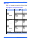
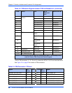
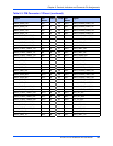
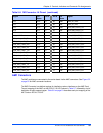
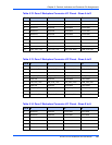
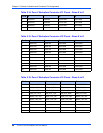
Table 5-6. FIM Connector J4 Pinout (continued)
Signal Pin
Name
Pin # Pin # Pin
Name
Signal