


www.mivec.co.nz
4G9 ENGINE (E-W) -
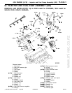
Injector and Fuel Pump Assembly (GDI)
11A-6c-7
"
I
A
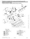
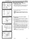
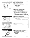
O-RING / BACKUP RING / FUEL PRESSURE
SENSOR INSTALLATION
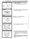
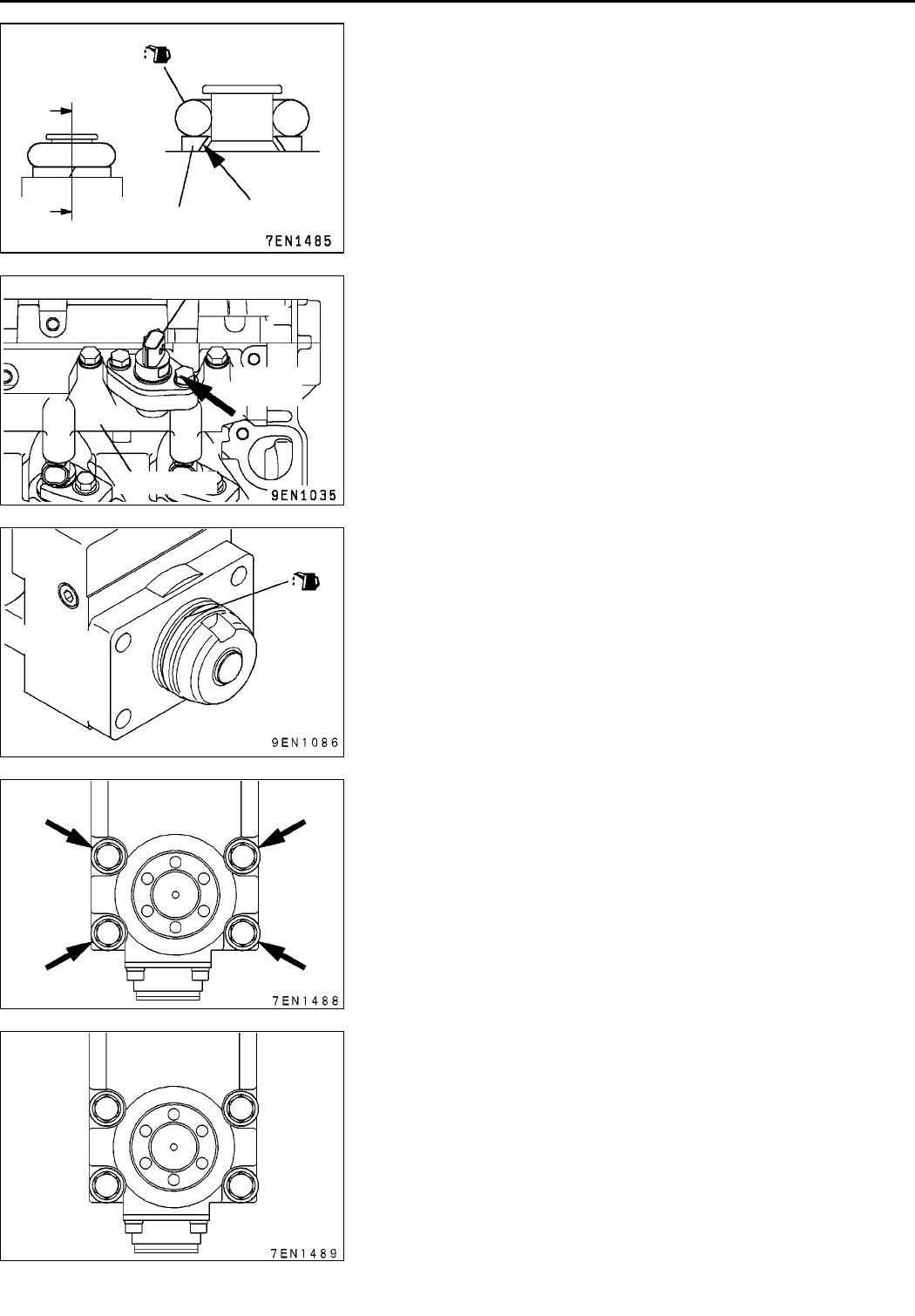
(1) Fit the backup ring to the fuel pressure sensor so that
its inner cut surface faces in the direction shown.
(2) Being attentive to the shape of the connector and label
surface of the fuel pressure sensor, install the fuel pressure
sensor in the direction shown.
"
J
A
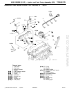
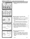
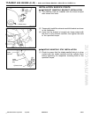
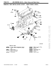
O-RING / FUEL PUMP INSTALLATION
(1) Apply engine oil to the O-ring.
(2) Insert the fuel pump into the mounting hole in the cylinder
head and lightly tighten the four bolts.
(3) Using a torque wrench (minimum graduations of 0.5 Nm),
follow these steps to tighten the fuel pump mounting bolts.
1) Tighten the bolts to 4.9 Nm in the order shown.
2) Tighten the bolts to 17
±
2 Nm in the order shown.
Variations in torque among the four bolts should be
within 2 Nm.
Caution
Strictly observe the tightening order. A leak and other
problem could result if the torque specifications and
torquing order are not met.
Backup ring
Cut surface
PWEE9502-H
E
July 2000MitsubishiMotors Corporation Revised
Label
surface
Fuel pressure sensor
Delivery pipe
1
4
3
2