


www.mivec.co.nz
4G9 ENGINE (E–W) – Crankshaft, Cylinder Block, Flywheel and Drive Plate
11A-12-1
PWEE9502-C
E
July 1997Mitsubishi Motors Corporation Revised
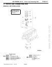
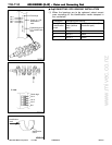
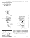
12. CRANKSHAFT, CYLINDER BLOCK, FLYWHEEL AND DRIVE PLATE
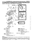
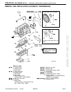
REMOVAL AND INSTALLATION (MANUAL TRANSMISSION)
SPACE STAR 10 Nm
Except SPACE STAR 11 Nm
98 Nm
11 Nm
13
14
15
16
17
18
21
8
3
4
5
6
7
9 Nm
19
23 Nm
20
9
12
11
10
<Engines with conventional
flywheel>
98 Nm
1
2
A
<Engines with flexible
flywheel>
Apply engine oil to all
moving parts before
installation.
Flange 10 Nm
Washer 9 Nm
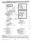
Removal steps
"FA 1. Flywheel bolt
2. Flywheel
"FA 3. Flywheel bolt
4. Plate
5. Adapter plate
6. Flywheel
7. Adapter plate
8. Rear plate
9. Bell housing cover
<4G92–SOHC, 4G93–SOHC>
"EA 10. Rear oil seal case
"DA 11. Oil seal
12. Baffle plate
<MIVEC engine manufactured from
Nov. 1995 to Dec. 1995>
"CA 13. Bearing cap bolt
"CA 14. Bearing cap
"BA 15. Crankshaft bearing, lower
16. Crankshaft
"BA 17. Thrust plate
"BA 18. Crankshaft bearing, upper
19. Knock sensor
<Except GALANT–CARBURETOR,
LANCER for Australia>
AA""AA 20. Oil jet
<DOHC–MIVEC>
21. Cylinder block
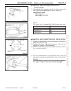
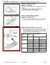
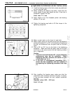
Caution
On the flexible wheel equipped engines, do not remove any of the bolts “A” of the flywheel shown
in the illustration.
The balance of the flexible flywheel is adjusted in an assembled condition. Removing the bolt,
therefore, can cause the flexible flywheel to be out of balance, giving damage to the flywheel.
PWEE9502-J
E
Apr. 2002Mitsubishi Motors Corporation Revised