


www.mivec.co.nz
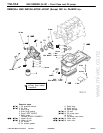
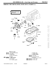
4G9 ENGINE (E–W) – Piston and Connecting Rod
11A-11-3
PWEE9502
E
May 1995Mitsubishi Motors Corporation
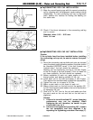
INSTALLATION SERVICE POINTS
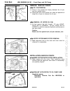
"AA PISTON PIN INSTALLATION
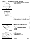
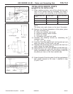
(1) When replacing a piston, read off the cylinder bore size
mark on the cylinder block as illustrated, and select a
piston of proper size according to the following table.
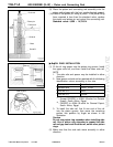
Cylinder bore size
mark
Piston class Piston size mark
A A A
B B None
C C C
NOTE
The piston size mark shows on the top of the piston.
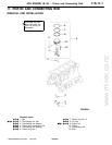
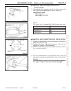
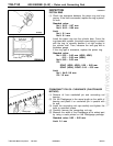
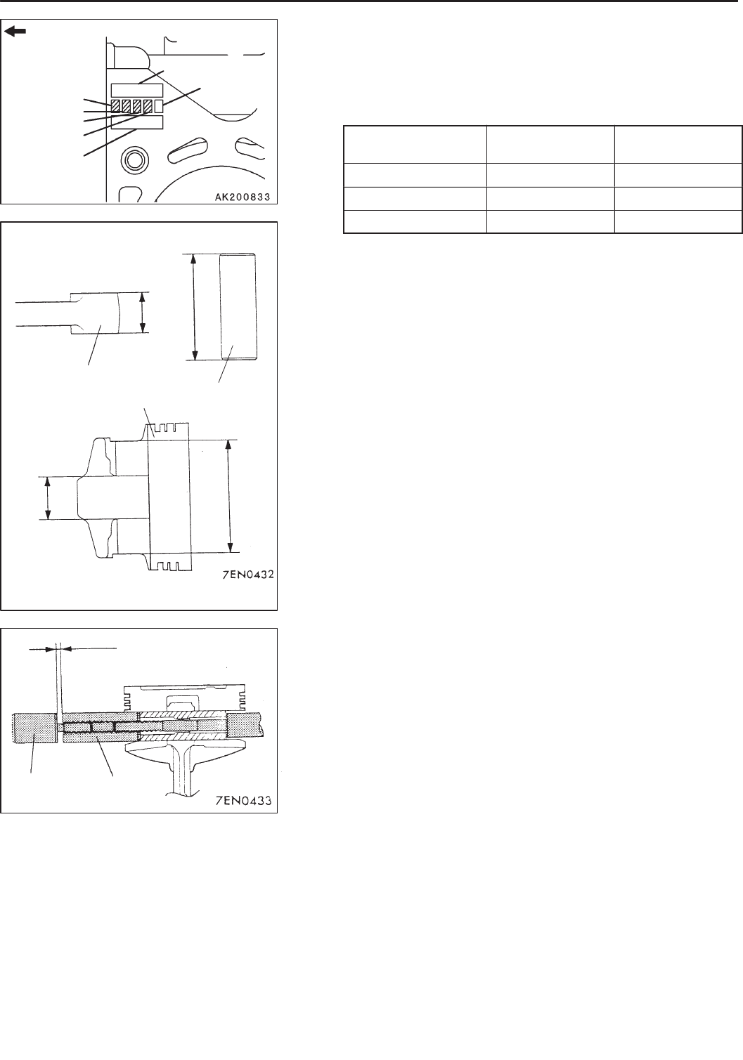
(2) Measure the following dimensions of the piston, piston
pin and connecting rod.
A: Piston pin insertion hole length
B: Distance between piston bosses
C: Piston pin length
D: Connecting rod small end width
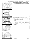
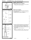
(3) Calculate the following formula by substituting the
measured value.
L = ((A – C) – (B – D))/2
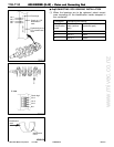
(4) Insert the Push Rod (special tool) into the piston pin and
attach the guide A to the push rod end.
(5) Assemble the connecting rod in the piston with their front
marks facing the same direction.
(6) Apply engine oil to the entire periphery of the piston pin.
(7) Insert the piston pin, push rod and guide A assembly
having assembled in step (3) from the guide A side into
the piston pin hole on the front marked side.
(8) Screw the guide B into the guide A until the gap between
both guides amounts to the value L obtained in step
(3) plus 3 mm.
PWEE9502-L
E
Apr. 2003Mitsubishi Motors Corporation Revised
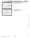
Timing belt side
Cylinder bore
size mark
Manufacturing date
Check digit
No. 1
No. 2
No. 3
No. 4
D
C
Connecting rod
Piston
Piston pin
B
A
3 mm + L
Guide B Guide A