


www.mivec.co.nz
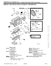
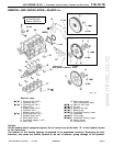
4G9 ENGINE (E–W) – Crankshaft, Cylinder Block, Flywheel and Drive Plate
11A-12-4
PWEE9502-A
E
Nov. 1995Mitsubishi Motors Corporation Revised
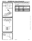
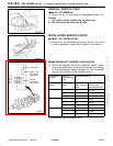
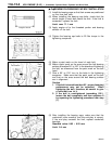
"CA BEARING CAP/BEARING CAP BOLT INSTALLATION
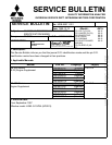
(1) Install the bearing caps so that their arrows are positioned
on the time belt side.
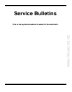
(2) When installing the bearing cap bolts, check that the
shank length of each bolt meets the limit. If the limit is
exceeded, replace the bolt.
Limit: max. 71.1 mm
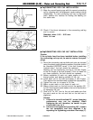
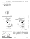
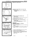
(3) Apply engine oil to the threaded portion and bearing
surface of the bolt.
(4) Tighten the bearing cap bolts to 25 Nm torque in the
tightening sequence.
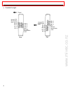
(5) Make a paint mark on the head of each bolt.
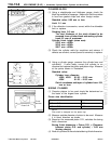
(6) Make a paint mark on the area around the bolt bearing
surface at location 90_ to 100_ in the direction of tightening
the bolt, as referenced from the paint mark on the bolt
head.
(7) Give a 90_ to 100_ turn to the bolts in the tightening
sequence. Make sure that the paint mark on the bolt
and that on the area around the bolt bearing surface
are in alignment.
Caution
1. If the bolt is turned less than 90_, proper fastening
performance may not be expected. When
tightening the bolt, therefore, be careful to give
a sufficient turn to it.
2. If the bolt is overtightened (exceeding 100_),
loosen the bolt completely and then retighten it
by repeating the tightening procedure from step
(1).
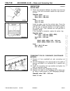
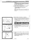
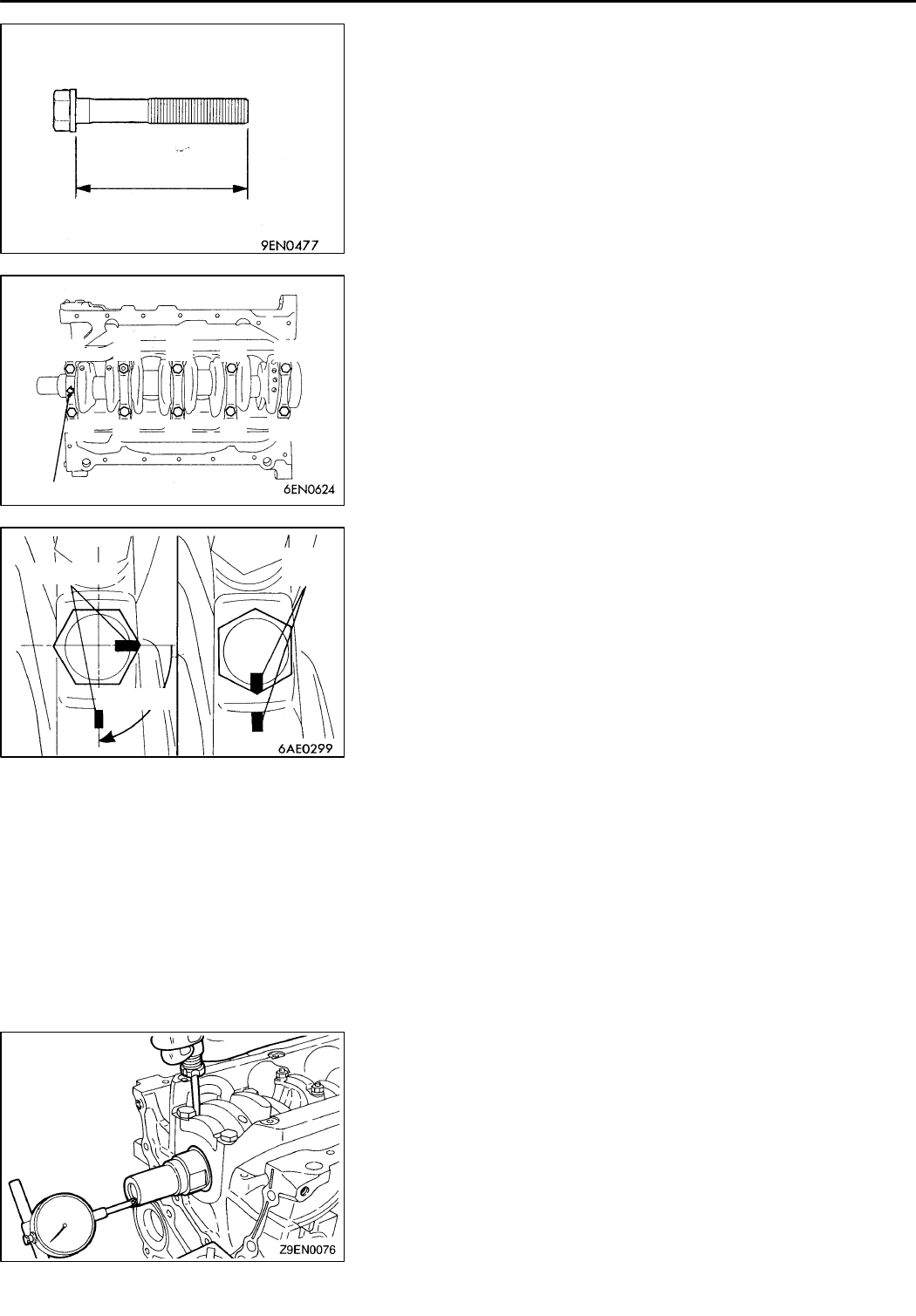
(8) After installing the bearing caps, make sure that the
crankshaft turns smoothly and the end play is correct.
If the end play exceeds the limit, replace crankshaft
bearings.
Standard value: 0.05 – 0.25 mm
Limit: 0.4 mm
PWEE9502-I
E
Mar. 2001Mitsubishi Motors Corporation Revised
Length of shank
(8) (4) (1)
(5) (9)
(7) (3) (2) (6) (10)
Arrow
90_ – 100_
Paint marks
Paint
marks