


www.mivec.co.nz
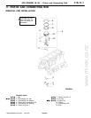
4G9 ENGINE (E–W) – Piston and Connecting Rod
11A-11-4
PWEE9502
E
May 1995Mitsubishi Motors Corporation
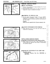
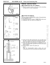
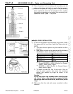
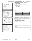
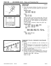
(9) Place the piston and connecting rod assembly onto the
piston setting base with the front marks directed upward.
(10)Press-fit the piston pin using a press. If the press-fitting
force required is less than the standard value, replace
the piston and piston pin set or/and the connecting rod.
Standard value: 4,500 – 14,700 N
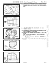
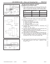
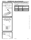
"BA OIL RING INSTALLATION
(1) Fit the oil ring spacer into the piston ring groove. Install
the upper side rail, and then install the lower side rail.
NOTE
1. The side rails and spacer may be installed in either
direction.
2. New spacer and side rail are painted with the following
identification colour according to the size.
Size Identification colour
Standard size None
∗
1
or red
∗
2
0.50 mm O.S. Blue
1.00 mm O.S. Yellow
∗
1
: Except PAJERO io 4G94–16-valve for General
Export, South Africa, Egypt
∗
2
: PAJERO io 4G94–16-valve for General Export,
South Africa, Egypt
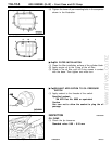
3. To install the side rail, first fit one end of the rail
into the piston groove, then press the remaining
portion into position by finger as shown in the
illustration.
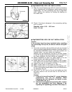
Caution
Do not use piston ring expander when installing side
rail. Use of piston ring expander to expand the side
rail end gap can break the side rail, unlike other piston
rings.
(2) Make sure that the side rails move smoothly in either
direction.
Push rod
Piston pin
Front
mark
Front mark
Guide A
Base
Guide B
PWEE9502-K
E
Jun. 2002Mitsubishi Motors Corporation Revised
Side rail
Spacer
Side rail end