


www.mivec.co.nz
4G9 ENGINE (E-W) -
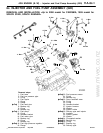
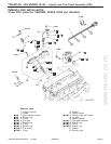
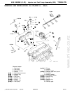
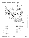
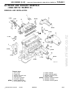
Injector and Fuel Pump Assembly (GDI)
11A-6c-4
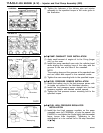
(8) Tighten the fasteners of the delivery pipe and injector
assembly to the specified torque in the order given in
the illustration.
"
C
A
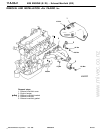
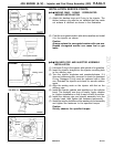
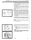
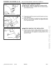
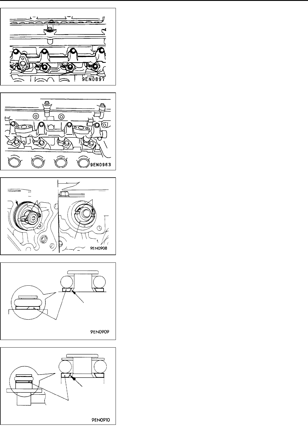
PUMP CAMSHAFT CASE INSTALLATION
(1) Apply small amount of engine oil to the O-ring (larger
one) on the case.
(2) Install the pump camshaft case onto the cylinder head
while aligning the coupling keys of the case with the
grooves in the rear end face of the camshaft.
NOTE
The coupling keys and t h e grooves at the camshaft rear
end are offset with respect to the camshaft center.
(3) Tighten the case mounting bolts to the specified torque.
"
D
A
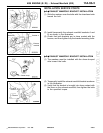
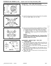
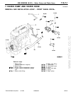
FUEL PRESSURE SENSOR INSTALLATION
(1) Install the backup ring to the fuel pressure sensor with
its inside cut surface in the illustrated direction.
(2) Install th e fuel pressure sensor straight into the fuel
pressure regulator with labeled surface upward.
(3) Tighten the fuel pressure sensor mounting bolt to the
specified torque.
"
E
A
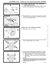
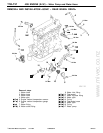
FUEL HIGH PRESSURE REGULATOR
INSTALLATION
(1) Install the fuel high pressure regulator on the pump
camshaft case <for CARISMA> or onto the spacer <for
PAJERO io> an d tighten the 3 bolts lightly (with somewhat
larger torque than fingertight). Tightening to the
specification is to be carried out in the step described
in "
F
A.
PWEE9502-E
E
Dec. 1998MitsubishiMotors Corporation Revised
1
2
3
4
<CARISMA>
<PAJERO io>
1
2
3
4
O-ring
Coupling
key
Groove
Camshaft
Backup ring
Cut surface
Backup ring
Cut surface