


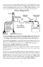

41
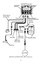
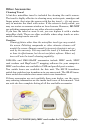
After drilling the hole, pass the transducer connector up through the
hole from under the dash, followed by antenna connector. Pass the
power cable's bare-wire end down though the hole from the top.
If you wish, you can fill in the hole around the cables with a good ma-
rine caulking compound. (Some marine dealers stock cable hole covers
to conceal the opening.) No matter what type of installation you prefer,
be sure to leave enough slack in the cables to allow tilting or swiveling
the unit. If you choose to fill in the hole, be sure to position the cables
against the rear edge of the hole as you apply the fill material.
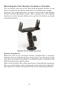
Before positioning the bracket, be sure to hold the cables against the
rear edge of the hole. Slide the bracket over the hole and butt the rear
of the bracket base against the cables, thus pinning them in place
against the side of the hole. Fasten the bracket to the dash. Attach the
unit to the gimbal bracket using the gimbal knobs and washers.
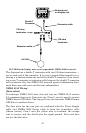
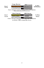
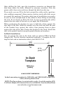
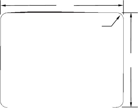
In-Dash Installation
You can mount the unit in the dash with an optional FM-5 In-Dash
Adapter Kit. The kit includes mounting hardware, a template for cut-
ting the hole and an instruction sheet, part 988-0147-43.
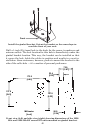
In-dash mounting template for LMS-520c and LMS-525cDF sonar/GPS
units, showing dimensions.
NOTE: The figure above is not printed to scale. A scaled template (FM-
5 In-Dash Adapter Kit instructions) is available for free download from
our web site, www.lowrance.com.
113.5
[4.46]
Millimeters
[Inches]
A
LWAYS VERIFY DIMENSIONS
In-Dash
Template
R 7.9
[0.31]
146.5
[5.76]
Top