


29
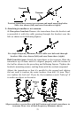
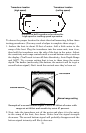
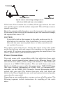
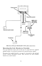
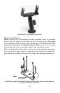
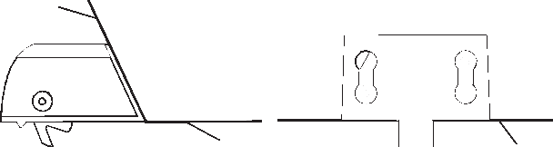
Speed sensor mounting configuration:
side view (left) and rear view (right.)
If the base of the transom has a radius, fill the gap between the tran-
som and the sensor with the sealant compound. This will help ensure a
smooth water flow.
Route the sensor's cable through or over the transom to the sonar unit.
If you need to drill a hole in the transom to pass the connector through,
the required hole size is 7/8".
CAUTION:
If you drill a hole in the transom for the cable, make sure it is lo-
cated above the waterline. After installation, be sure to seal the
hole with the same marine grade above- or below-waterline seal-
ant used for the screws.
The sensor is now ready for use. Connect the sensor to the sonar socket
on the back of your unit and connect the transducer to the speed sen-
sor's socket. If you have any questions concerning the installation of the
sensor, please contact your local boat dealer.
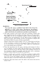
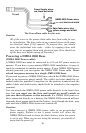
Power Connections
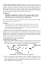
Your unit comes with a power/data cable that splits into three ends,
each with several exposed wires (shown in the following figure). The
end with 4 wires (blue, yellow, orange and shield) is a Data cable that
connects to a NMEA 0183 interface. The end with three wires (red,
black and shield) is a power cable that connects to a NMEA 2000
buss.
(For more detailed information on NMEA 2000 or LowranceNET
networks, see the NMEA 2000 Networks General Information booklet
packed with your unit.) The thicker three-wire cable (red, black and
white) is the Power Supply for your unit (and optional external speaker
connection for some units).
Depending on your configuration, you may not use all of the wires. The
following segments include instructions for installing all the unit's
wires.
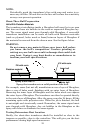
Transom
Bottom of hull
Bottom of hull