


13
Section 2: Installation
Preparations
You can install the unit in some other order if you prefer, but we rec-
ommend this installation sequence:
Caution:
You should read over this entire installation section before drill-
ing any holes in your vessel!
1. Determine the approximate location for the unit, so you can plan how
and where to route the cables for the transducer, any sensor and power.
This will help you make sure you have enough cable length for the de-
sired configuration.
NOTE:
The GPS antenna is inside the unit, so you must mount the unit in
a location with an unobstructed view of the sky.
2. Determine the approximate location for the transducer, any sensor
and their cable routes.
3. Determine the location of your battery or other power connection,
along with the power cable route.
4. Install the transducer and route the transducer cable to the sonar
unit. Install the speed or temp sensor, if applicable, and route the cable
to the unit.
5. Route the power cable from the unit's location to an appropriate
power source and connect it there.
6. Connect the transducer/power cable (and any sensor cables) to the
unit and mount the unit on the bracket.
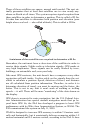
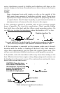
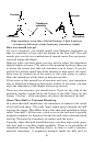
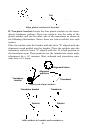
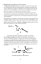
Transducer Installation
These instructions will help you install your Skimmer
transducer on a
transom, on a trolling motor or inside a hull. These instructions cover
both single- and dual-frequency Skimmer transducers. Please read all
instructions before proceeding with any installation.
The smaller single-frequency Skimmers typically use a one-piece,
stainless steel mounting bracket. The larger dual-frequency Skimmers
typically use a two-piece, plastic mounting bracket. The optional troll-
ing motor mount uses a one-piece plastic bracket with an adjustable
strap.
These are all "kick-up" mounting brackets. They help prevent damage if
the transducer strikes an object while the boat is moving. If the trans-