


22
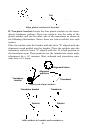
6. Route the transducer cable through or over the transom to the so-
nar unit. Make sure to leave some slack in the cable at the transducer. If
possible, route the transducer cable away from other wiring on the boat.
Electrical noise from the engine's wiring, bilge pumps, VHF radio wires
and cables, and aerators can be picked up by the sonar. Use caution
when routing the transducer cable around these wires.
WARNING:
Clamp the transducer cable to the transom close to the
transducer. This can prevent the transducer from enter-
ing the boat if it is knocked off at high speed.
If you need to drill a hole in the transom to pass the connector through,
the required hole size will be 5/8".
Caution:
If you drill a hole in the transom for the cable, make sure it is lo-
cated above the waterline. After installation, be sure to seal the
hole with the same marine grade above- or below-waterline seal-
ant used for the mounting screws.
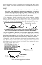
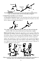
7. Make a test run to determine the results. If the bottom is lost at
high speed, or if noise appears on the display, try sliding the transducer
bracket down. This puts the transducer deeper into the water, hope-
fully below the turbulence causing the noise. Don't allow the transducer
bracket to go below the bottom of the hull!
Trolling Motor Bracket Installation
(single-frequency only)
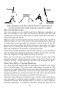
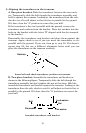
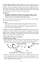
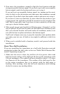
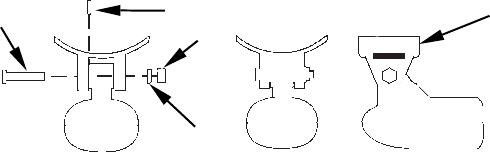
1. Attach the optional TMB-S bracket to the transducer as shown in the
following figure, using the hardware supplied with the transducer.
(Note: The internal tooth washer is supplied with the TMB-S.)
Attach motor mounting bracket to transducer.
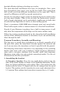
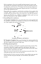
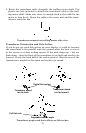
2. Slide the adjustable strap supplied with the TMB-S through the slot
in the transducer bracket and wrap it around the trolling motor. Po-
sition the transducer to aim straight down when the motor is in the
water. Tighten the strap securely.
TMB-S bracket
Bolt
Internal tooth washer
Nut
Flat washer