


28
Speed/Temperature Sensors
Optional Speed Sensor Installation
All the units in this series can display speed and distance traveled, but
only the LMS-339cDF iGPS comes packed with a speed sensor. If you
want to purchase an optional additional sensor for your unit, refer to
the accessory ordering information inside the back cover of this man-
ual. The following instructions describe how to install the speed sensor.
Recommended tools for this job include: drill, 7/8" drill bit, 1/8" drill bit
for pilot holes, screwdriver. Required supplies for this job include: four
#8 stainless steel wood screws (3/4" long), high quality, marine grade
above- or below-waterline sealant.
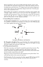
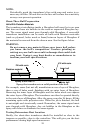
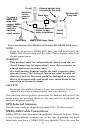
First find a location on the boat's transom where the water flow is
smoothest. Don't mount the sensor behind strakes or ribs. These will
disturb the water flow to the speed sensor. Make sure the sensor will
remain in the water when the boat is on plane. Also make sure the lo-
cation doesn't interfere with the boat's trailer. Typically, the sensor is
mounted about one foot to the side of the transom's centerline.
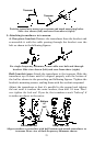
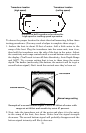
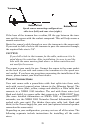
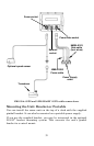
Once you've determined the proper location for the unit, place the sen-
sor on the transom. The bottom of the bracket should be flush with the
hull's bottom. Using the sensor as a template, mark the hull for the
screws' pilot holes. Drill four 1/8" holes, one in each end of the slots.
Mount the sensor to the hull using #8 stainless steel wood screws (not
included). Use a high quality, marine grade above- or below-waterline
sealant to seal the screws. Make sure the sensor is flush with the bot-
tom of the hull and tighten the screws.
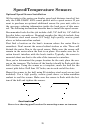
Stern view showing good location for mounting sensor on transom.
Good location