


Garmin G1000 Cockpit Reference Guide for the Mooney M20M, M20R, & M20TN
2-6
SECTION 2
FLIGHT INSTRUMENTS
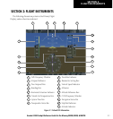
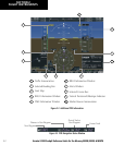
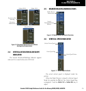
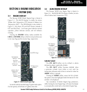
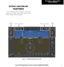
2.7 HORIZONTAL SITUATION INDICATOR
(HSI)
Figure 2-12 Horizontal Situation Indicator
8
14
9
6
5
4
3
2
1
7
13
12
11
10
Heading Bug
2
3
6
4
5
7
1
Turn Rate Indicator
Navigation Source
Course Deviation Indicator
TO/FROM Indicator
Course Pointer
Rotating Compass Rose
11
10
12
13
14
9
8
OBS Mode
Lateral Deviation Scale
Flight Phase
Aircraft Symbol
Lubber Line
Heading
Turn Rate and Heading Trend Vector
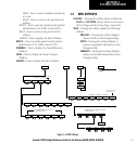
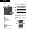
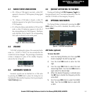
Arc HSI
The HSI compass can be displayed as a 360° rose or
140° arc (see Figure 2-15) by pressing the PFD Softkey,
followed by the 360 HSI or the ARC HSI Softkey.
NOTE: When the Arc HSI is displayed, the BRG1
and BRG2 information windows and pointers are
disabled.
NOTE: If the pilot makes a heading change
greater than 105˚ with respect to the course, the
CDI switches to the opposite side of the deviation
scale and displays reverse sensing.
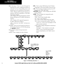
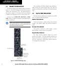
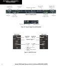
Turn Rate Indicator and Heading Trend Vector
Tick marks to the left and right of the lubber line
denote half-standard and standard turn rates. A magenta
turn rate trend vector shows the current turn rate. The
end of the trend vector gives the heading predicted in six
seconds, based on the present turn rate. At rates greater
than 4 deg/sec, an arrowhead appears at the end of the
magenta trend vector and the prediction is no longer
valid.
Figure 2-14 Standard-Rate Turn Indication
Turn Rate
Trend Vector
(standard rate)
Figure 2-13 Turn Rate Indicator and Trend Vector
Half-Standard Turn
Rate Tick Mark
Standard Turn
Rate Tick Mark
Turn Rate
Trend Vector
(rate > 4
deg/sec)