


Garmin G1000 Cockpit Reference Guide for the Mooney M20M & M20R
SECTION 3 – ENGINE
INDICATION SYSTEM (EIS)
3-2
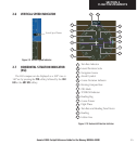
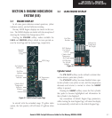
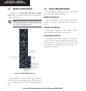
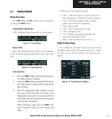
3.3 ENGINE SYSTEM DISPLAY
If desired, use the DEC FUEL, INC FUEL and RST
FUEL softkeys to adjust the amount of fuel remaining for
totalizer calculations.
NOTE: Fuel calculations do not use the aircraft
fuel quantity indicators, and are calculated from
the last time the fuel was reset.
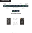
Fuel Remaining
Flap
Position
Figure 3-3 M20R SYSTEM Engine Page
Aircraft Total
Time in Service
Elevator Trim
Takeoff Position
Rudder Trim
Takeoff Position
Trim Position
Indicator
Any exceedance of default Engine Page parameters,
while viewing the System Engine Page, will cause the dis-
play to automatically switch back to the default Engine
Page.
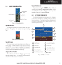
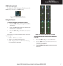
3.4 FLAP & TRIM INDICATIONS
The flap and trim indicators are located on the MFD
next to the engine indicating displays.
Rudder Trim Indicator
Actual trim position is shown using a blue inverted
triangle. The ‘takeoff’ rudder trim position is shown in
white.
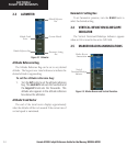
Elevator Trim Indicator
Trim position is shown by a blue triangle. A white
block indicates ‘takeoff’ elevator trim position.
Flaps Position Indicator
The Flaps Position Indicator shows the current posi-
tion of the flaps. The three possible positions, up, take-
off, and down, are depicted in cyan as ‘UP’, ‘T/O’, and
‘DN’, respectively. During flaps position transition, ‘///’ is
displayed in the window.