


Garmin G1000 Cockpit Reference Guide for the Mooney M20M & M20R
2-3
SECTION 2
FLIGHT INSTRUMENTS
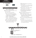
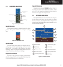
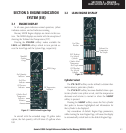
2.1 AIRSPEED INDICATOR
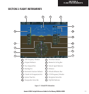
Figure 2-4 Airspeed Indicator
Actual Airspeed
Airspeed Trend
Vector
True Airspeed
Box
Speed Ranges
Vspeed
References
Speed Indication
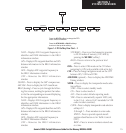
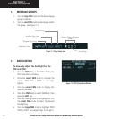
The indicated airspeed is displayed inside the black
pointer. The pointer will become red upon reaching
Vne.
Figure 2-5 Red Pointer at Vne
Speed Ranges
The color coded speed range strip denotes flaps op-
erating range, normal operating range, and never exceed
speed (Vne). A red range is also present for low speed
awareness. Refer to the Airplane Flight Manual (AFM) for
airspeed limitations and indicator markings.
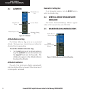
Airspeed Trend Vector
The end of the trend vector displays approximately
what the airspeed will be in 6 seconds if the current rate
of acceleration/decelaration is maintained.
Vspeed References
Vspeeds are set using the TMR/REF softkey. Glide, Vr,
Vx and Vy are shown on the References window. When
active (ON), the Vspeeds are displayed at their respective
locations to the right of the airspeed scale.
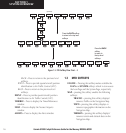
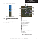
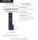
2.2 ATTITUDE INDICATOR
The Slip/Skid Indicator is located under the roll point-
er and moves laterally away from the pointer to indicate
lateral acceleration. One Slip/Skid indicator displacement
is equal to one ball displacement when compared to a tra
-
ditional slip/skid indicator.
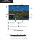
Figure 2-6 Attitude Indicator
3
2
1
9
8
7
6
5
4
1
2
3
4
5
Roll Scale
Horizon Line
Aircraft Symbol
Land Representation
Roll Pointer
6
7
8
9
Aircraft Wing Tips
Pitch Scale
Sky Representation
Slip/Skid Indicator
Roll Index
10
10