


Garmin G1000 Cockpit Reference Guide for the Mooney M20M & M20R
2-6
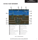
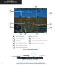
SECTION 2
FLIGHT INSTRUMENTS
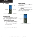
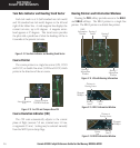
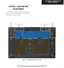
Turn Rate Indicator and Heading Trend Vector
Each tick mark is at 9 (half standard rate tick mark)
and 18 (standard rate tick mark) degrees to the left and
right of the lubber line. A wide magenta line displays the
current turn rate, up to 24 degrees. A magenta arrow-
head appears at 25 degrees. This trend vector provides
the pilot with a prediction of what the heading will be in
6 seconds at the present turn rate.
Figure 2-14 Turn Rate Indicator and Heading Trend Vector
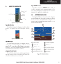
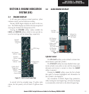
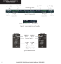
Course Pointer
The course pointer is a single line arrow (GPS, VOR1
and LOC1) or double line arrow (VOR2 and LOC2) which
points in the direction of the set course.
Lateral Deviation
Scale
Figure 2-15 Arc CDI and Compass Rose CDI
Course Deviation
TO/FROM Indicator
Course Deviation Indicator (CDI)
The CDI scale automatically adjusts to the current
phase of flight (enroute 5.0 nm, terminal area 1.0 nm,
or approach 0.3 nm). Scaling may be selected manually
from the MFD System Setup Page.
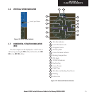
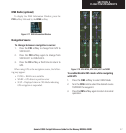
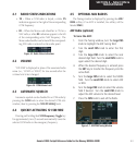
Bearing Pointers and Information Windows
Pressing the PFD softkey provides access to the BRG1
and BRG2 softkeys. The BRG1 pointer is a single line
pointer. The BRG2 pointer is a double line pointer.
Bearing 2
Pointer
Bearing 1
Information
Window
Bearing 1
Pointer
Bearing 2
Information
Window
Figure 2-14 HSI with Bearing Information
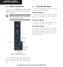
DME
Information
Window
Distance to
Bearing Source
Waypoint
Identifier
Bearing
Source
Pointer
Icon
Figure 2-15 BRG1 Information Window
Distance to
Bearing Source
Waypoint
Identifier
Pointer
Icon
Bearing
Source
Figure 2-16 BRG2 Information Window