


2-1
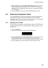
2. RADAR OPERATION
This chapter covers radar operation, including the ARP (Auto Plotter) function.
ARP requires a Model 1800/1900 series network radar equipped with the ARP
circuit board.
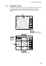
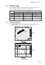
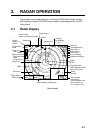
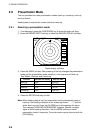
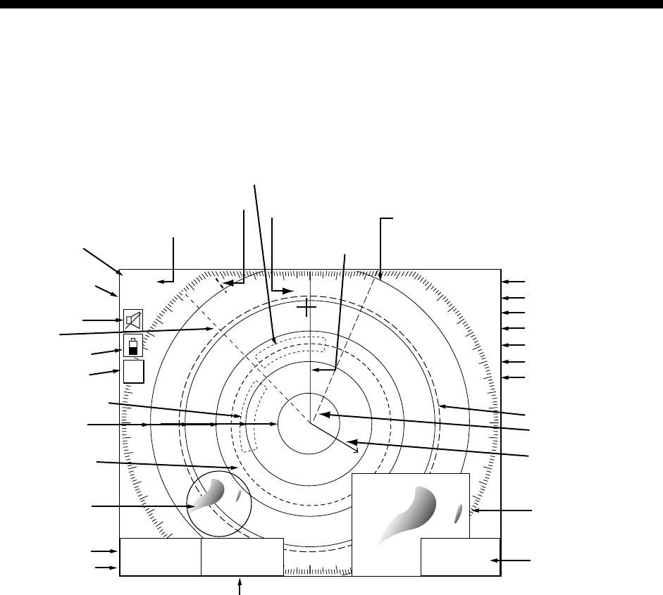
2.1 Radar Display
TRAIL 30m
02m30s
G1 IN
G2 OUT
ES 2
EAV L
IR L
EBL1
27.0°R
VRM1
5.666nm
Range/
range ring
interval
Presentation
mode
Zoom area
Zoom
window
Guard zone 1
Trail time
Trail elapsed time
Guard zone 1
Guard zone 2
Echo stretch
Interference rejector
Guard zone 2
VRM2
VRM1
EBL1
Range ring
Pulselength
Heading
M: Magnetic
T: True
Heading line
EBL1 bearing
VRM1 range
Cursor range
and bearing
(Cursor position may
also be shown, in
L/L or Loran C TD.)
EBL2 bearing, VRM2 range
Cursor
Alarm icon
Battery icon
EBL2
327.1°R
VRM2
8.212nm
12/
H-UP
3nm
LP
319. 9
°M
EBL2
Echo averaging
359.9 ˚R
11.70
nm
+
Own ship vector
(ARP-equipped model,
true vector mode)
North marker
(Head-up, Course-up mode)
S
I
M
Simulation
mode
Radar display