


9
INSTALLATION
SAFETY PRECAUTIONS
WARNING
Installation and service instructions for
use by qualified personnel only. To avoid
injury and electric shock do not perform
any servicing other than contained in the
operation instructions unless qualified.
STORAGE INFORMATION
The drive should be stored in its shipping
carton in a clean, dry area.
If it is necessary to store the drive outdoors for
a long period of time, it should be removed from
its shipping carton and stored above ground. A
waterproof cover should be securely fastened
over it. Do not stack drives on top of one another.
Stored drives should be periodically checked to
make sure no condensation has formed in the
control compartments. Damage due to moisture
while in storage is not covered by warranty.
UNPACKING
Group 14 drives are packed in standardized
cardboard shipping containers. Drives mounted
on valves may be packed in cardboard containers
or strapped to a skid and crated, depending on
size. After unpacking, the wooden platform may
be used to transport the drive to the installation
site.
INSTALLATION—MECHANICAL
Beck drives can be furnished with valves
mounted as unitized assemblies ready for
pipeline installation.
CAUTION
Whenever a control drive is being mounted
on a valve, it is good practice to remove the
valve from service. Observe the following
precautions:
• Know what fluid is in the line.
• Wear the proper protective equipment.
• Disconnect the electrical power.
• Depressurize the pipeline.
• Refer to the valve maintenance manual for
specific instructions.
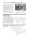
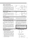
Figure 1
Mounting The Drive On A Valve
Refer to Figure 1, below, to identify the
mounting parts and the steps to install the drive
onto the valve.
1. Prepare the valve. It may be necessary to
remove parts that are no longer used or to
replace or adjust packing. Refer to the valve
maintenance manual for specific instructions.
Consult the Beck Valve Mounting Specification
sheet that was shipped with the drive for any
instructions regarding modifications to the
valve stem that may be necessary.
2. Push the valve stem (11) into the valve body
to the fully seated or stem down position.
3. Move the G-14 output shaft (5) up into the
drive body until the upper mechanical stop (3)
is tight against the lower bearing plate (1).
4. Remove the four lower bearing plate bolts
(2) that hold the bottom plate to the drive
body (1/2" bolt heads). Pressure from the
mechanical stop will hold the plate in place
when the bolts are removed. Bolt the yoke
(9) to the lower bearing plate using the longer
bolts supplied with the yoke. Torque bolts to
10 Ib-ft.
Continued