


25
CHANGING DIRECTION OF
TRAVEL
Retracting direction of travel is defined as the
direction of output shaft motion produced by an
increasing signal. Unless otherwise specified at
the time of order, the output shaft is factory set
to retract in response to an increasing signal to
open the valve.
The procedure to change the direction of
travel of the output shaft varies by model number.
The model number is listed on the drive name
plate. Determine the model number and refer to
one of the following procedures.
CAUTION
Be sure the drive is disconnected from the
line voltage and that all auxiliary switches
are disconnected from the external power
sources before beginning the direction
change procedure.
Models 14-_03 and 14-_04
1. Remove the top cover (15/16" bolt head).
The O-ring seal will remain in the rim of the
top cover when removed.
2. Interchange the yellow and black wires on the
common terminals of the RET and EXT travel
limit switches.
3. Replace the top cover. Tighten the cover bolt
just enough to compress the O-ring seal.
Models 14-_05 and 14-_07
NOTE: On model 14-107 units equipped with
an auxiliary film potentiometer, the auxiliary
potentiometer is mounted closest to the
sector gear end of the control shaft.
1. Remove the top cover (15/16" bolt head).
The O-ring seal will remain in the rim of the
top cover when removed.
2. For model 14-_07, interchange the wire
jumpers connected to terminals M and N.
3. Interchange the wires connected to the ends
of the potentiometer. The wire on terminal
1 or 5 should be moved to the opposite
terminal. Also move the wire on terminal 2
or 4 to the opposite terminal. The wire to
terminal 3 remains unchanged.
Auxiliary Potentiometer Only
4. Reverse the wires connected to the ends of
the potentiometer. The wire on terminal 1 or 5
or on terminal 2 or 4 should be moved to the
opposite terminal.
CALIBRATION CHANGING DIRECTION OF TRAVEL
5. Replace the top cover. Tighten the cover bolt
just enough to compress the O-ring seal.
Models 14-_06 and 14-_08
1. Open the terminal compartment (1/2" bolt
heads) and remove the top cover (15/16" bolt
head). The O-ring seal will remain in the rim
of the top cover when removed.
2. For model 14-_08, interchange the wire
jumpers connected to terminals M and N.
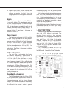
3. Install a mA meter in series with a 200 ohm
load resistor for current outputs or a voltmeter
across the CPS-2 output terminals for voltage
outputs (see Table 11, page 46).
4. Reconnect drive power.
5. Drive the output shaft until the CPS-2 output
is 50% of the range (e.g. for 4–20 mA signal
range, set output to 12 mA).
6. Set Handswitch to STOP position.
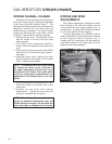
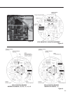
7. Using a 7/64” hex wrench, loosen the CPS-2
rotor clamp.
8. Rotate the CPS-2 rotor 180° and set the
output back to the mid-range (e.g. 12 mA).
9. Tighten rotor clamp (see Figure 8, page 29).
10. Run the drive to the retract and extend limits with
the Handswitch. Record CPS-2 output at limits.
11. Subtract outputs recorded at the two limits
and compare with the desired output signal
span (e.g., 16 mA or 4 V dc).
12. Move the drive to the retract limit.
13. Divide the difference between the measured
span, step 11, and the desired span by
2. Adjust the Span Potentiometer by this
amount (see Figure 9, page 29). NOTE: CW
movement of the Span Potentiometer moves
the ends of the signal range away from each
other, while CCW movement moves the ends
of the signal range toward each other.
14. Loosen the rotor clamp and adjust the rotor
position to achieve the desired value of
maximum output signal (e.g. 10 mA or 5 V
dc). NOTE: Rotor adjustment moves the
entire signal span up or down.
15. Tighten rotor clamp and run output shaft to
retract and extend limits to check CPS-2 signal
for desired span. If incorrect, repeat step 11.
16. Tighten rotor clamp to 5 Ib-in torque. Maintain
0.031 inch clearance between rotor clamp
and stator.
17. Remove meter and resistor and reconnect
output wiring.
18. Close covers and tighten the terminal cover
bolts to 10 Ib-ft torque. Tighten the top cover
just enough to compress the O-ring seal.
19. Model 14-_08: Recalibrate ESR-4 Board.