


37
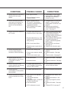
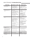
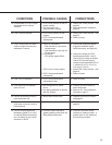
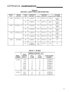
CONDITIONS
POSSIBLE CAUSES
CORRECTIONS
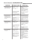
5. Control drive runs in the wrong
direction with input signal
applied.
6. Control drive does not follow
input signal until maximum or
minimum signal is reached,
then drives uncontrollably to
limit.
7. Control drive motor oscillates in
AUTO mode.
8. Control drive motor erratic
or runs in wrong direction in
automatic or manual operation.
9. Control drive will not run in
either direction or one direction
in automatic or manual
operation.
10. Control drive erratic while
closing valve and runs normally
while opening in AUTO.
11. Control drive runs
uncontrollably to some position,
then oscillates.
12. Control drive does not stop at
normal or desired limit of shaft
travel.
a. Input signal reversed.
b. Drive configured for wrong
direction of travel.
a. Yellow and black wires on
RET and EXT limit switches
reversed or potentiometer end
connections reversed.
b. CPS-2 feedback out of phase
with control motor.
a. Feedback potentiometer dirty.
b. Excessive noise on input signal.
c. Physical obstruction (e.g., valve
jammed or load greatly exceeds
rating of drive).
d. ESR-4 circuit board failure.
e. Excessive wear in gear train or
bearings.
a. Control motor winding open.
b. Control motor capacitor shorted
or open.
c. Control motor resistor open.
a. Limit switch failure.
b. Handswitch failure.
a. Feedback potentiometer dirty.
Loss of feedback voltage drives
the unit in RET direction.
a. Feedback potentiometer open.
a. ESR-4 span or zero adjusted
incorrectly.
b. Limit switches adjusted
incorrectly.
c. Loss of input signal. Check LED
on ESR-4 circuit board.
d. Limit switch failure.
e. CPS-2 calibration incorrect.
a. Check polarity of input signal.
Terminal AA (+), terminal BB (-).
b. See page 25 for changing
direction of travel.
a. Change direction of travel; see
page 25. Check correct film
potentiometer connections; see
page 26.
b. Restore proper phasing of
CPS-2 feedback with control
motor. See page 27.
a. Clean or replace potentiometer.
b. Check setting of input filter. May
require lower gain setting if
oscillation remains with maximum
filter setting; see page 31.
c. Check operation with Handswitch
and remove obstruction if
present. Handswitch bypasses
ESR-4 board.
d. Replace ESR-4 circuit board.
See page 35.
e. Replace worn drive train parts.
a. Replace control motor. See
page 33.
b. Replace capacitor. See page
33.
c. Replace resistor. See page 33.
a. Replace limit switch. See page
34.
b. Replace Handswitch. See page
35.
a. Clean feedback potentiometer
with mild soap and water.
a. Replace feedback potentiometer.
a. Recalibrate ESR-4 board. See
page 30.
b. Readjust limit switches. See
page 22.
c. Restore input signal to control
drive.
d. Replace limit switch. See page
34.
e. Calibrate CPS-2; see page 27.